
Steam flow excitation fault real-time diagnosis method for large steam turbine-generator

A steam turbine generator set, steam flow excitation technology, applied in the field of mechanical vibration state monitoring and fault diagnosis, can solve the problems of long cycle, reduced shafting stability, high economic cost of diagnosis, etc., and achieve the effect of scientific method and reliable conclusion

Inactive Publication Date: 2009-04-08
NORTH CHINA ELECTRIC POWER UNIV (BAODING)
View PDF0 Cites 20 Cited by
  • Summary
  • Abstract
  • Description
  • Claims
  • Application Information

AI Technical Summary

Problems solved by technology

[0002] With the continuous increase of the capacity of the turbogenerator unit, the operating parameters of the unit continue to increase, and the pressure series of the unit continues to increase. The increase in the series makes the rotor span longer, the critical speed becomes lower, and the stability of the shaft system These factors can easily lead to steam flow excitation failures of high-parameter units, which mainly lead to the failure of the unit to continue to increase the load and fail to generate power at full load. This failure often occurs in large-capacity, high-parameter steam turbine power generation with initial parameters above 200MW In the unit, sometimes it may also appear in the design, installation, maintenance and operating conditions of the small-capacity unit
If the unit cannot generate electricity at full load, it will directly affect the economic benefits of the enterprise and become a problem affecting the safety and economy of the unit
However, the diagnosis of steam flow excitation is done by experienced experts, and the diagnostic cost is high and the cycle is long

Method used


Image

  • Steam flow excitation fault real-time diagnosis method for large steam turbine-generator
  • Steam flow excitation fault real-time diagnosis method for large steam turbine-generator
  • Steam flow excitation fault real-time diagnosis method for large steam turbine-generator

Examples


Embodiment

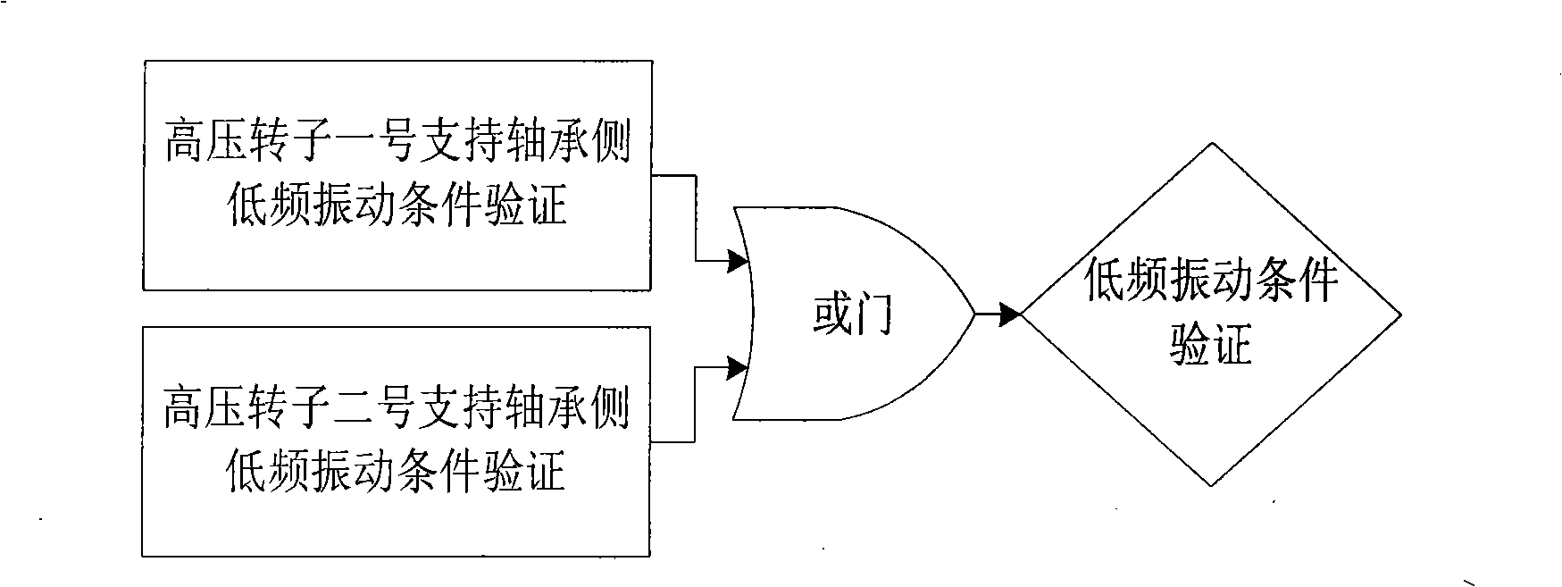
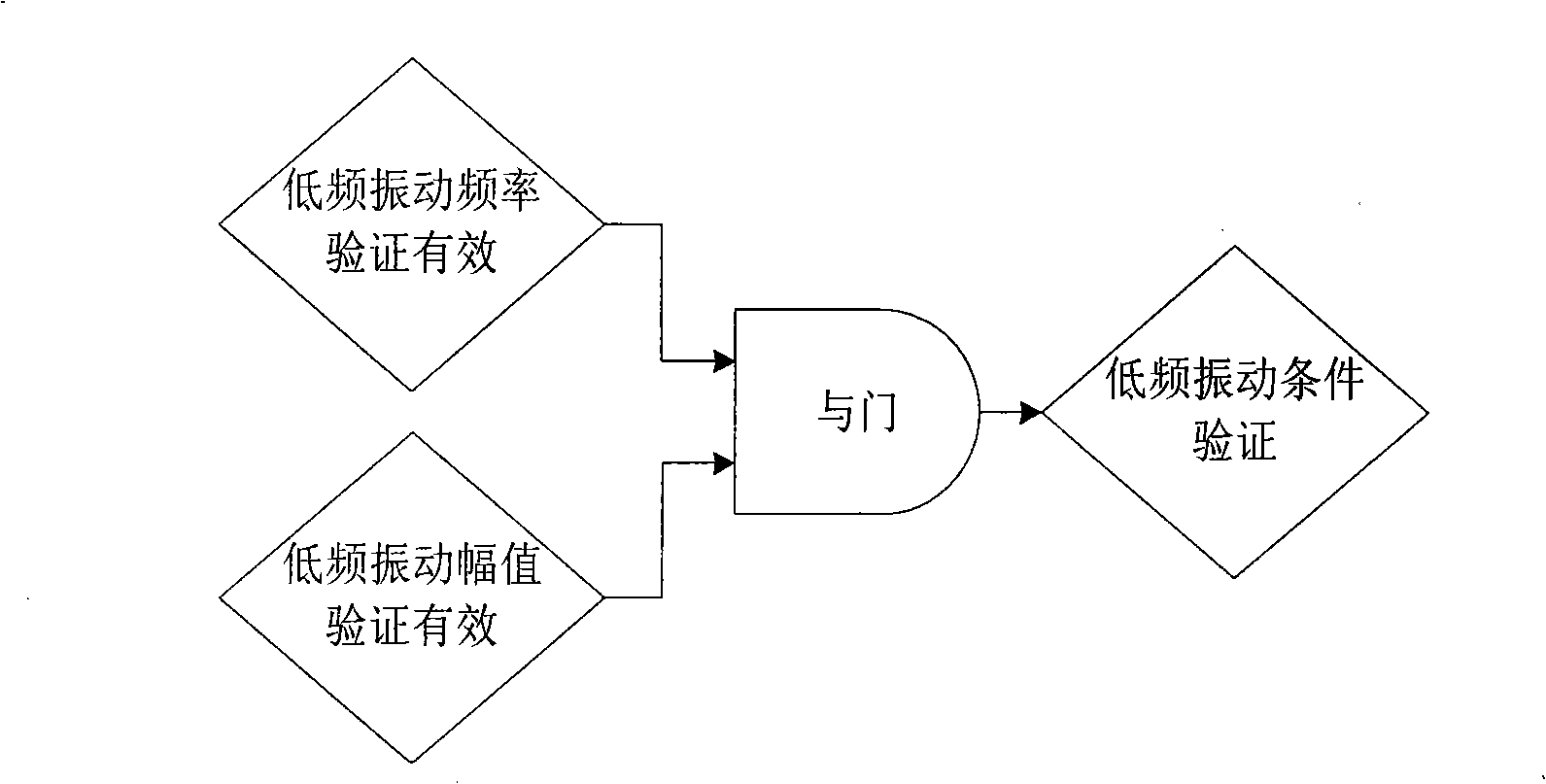
[0043] This method can be used to realize the fault diagnosis of steam flow excitation of 300MW turbogenerator set, one of the main power units in the current domestic power grid. According to this method, a specific computer diagnosis program for the steam-excited vibration fault is designed, and the fault diagnosis program is installed in the industrial computer (IPC). A diagnosis cycle process in the steam flow excitation fault diagnosis program includes a series of calculation and analysis verification links in the diagnosis method, such as data acquisition, data preprocessing, low-frequency vibration condition verification, unit load condition verification, and fault diagnosis decision-making.

[0044] First of all, the steam flow excitation fault diagnosis program in the industrial computer (IPC) collects the unit-related data required for diagnosis in real time through the high-speed data acquisition card. The vibration data to be collected is mainly supported by No. 1 a...


PUM


Abstract

The invention discloses a flow-excitation failure real-time diagnosis method used for a large-scale steam-turbine generator unit, belonging to the vibration-state real-time on-line automatic detection for the large-scale steam-turbine generator unit in the mechanical vibration-state detection and failure diagnosis field. The failure diagnosis method comprises the sections of data collection, data preprocessing, low-frequency vibration condition verification, unit load condition verification and failure diagnosis and the like. Whether the unit suffers the flow-excitation failure is diagnosed according to the results of low-frequency vibration condition verification and unit load condition verification. The method has the advantages that the diagnosis is reliable; and the automatic real-time on-line detection and failure diagnosis can be realized and the like.

Description

technical field [0001] The invention belongs to the field of mechanical vibration state monitoring and fault diagnosis, and in particular relates to a real-time diagnosis method for steam flow excitation fault of a large-scale turbo-generator set for real-time on-line automatic monitoring of the vibration state of a large-scale turbo-generator set. Background technique [0002] With the continuous increase of the capacity of the turbogenerator unit, the operating parameters of the unit continue to increase, and the pressure series of the unit continues to increase. The increase in the series makes the rotor span longer, the critical speed becomes lower, and the stability of the shaft system These factors can easily lead to steam flow excitation failures of high-parameter units, which mainly lead to the failure of the unit to continue to increase the load and fail to generate power at full load. This failure often occurs in large-capacity, high-parameter steam turbine power ge...

Claims


Application Information

Patent Timeline
IPC IPC(8): G01M7/02
Inventor 宋光雄顾煜炯
Owner NORTH CHINA ELECTRIC POWER UNIV (BAODING)
Learn More