Display apparatus and its method for regulating color resistance of color filter
A color filter and display technology, which is applied to the display device with a white light diode backlight module and the field of adjusting the color resistance of the color filter, which can solve problems such as color failure to meet requirements, and achieve the effect of improving color performance
- Summary
- Abstract
- Description
- Claims
- Application Information
AI Technical Summary
Problems solved by technology
Method used
Image
Examples
no. 1 example
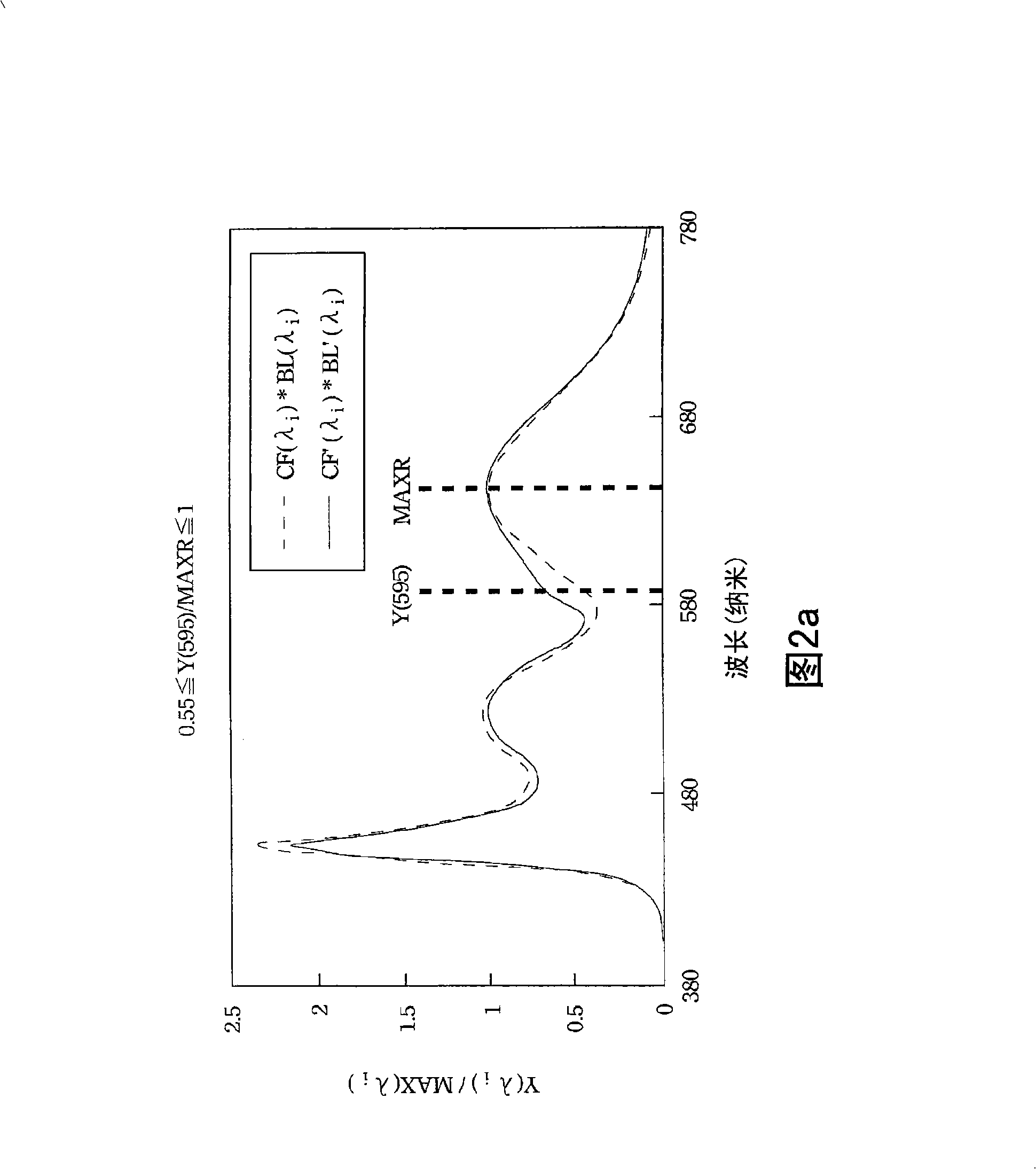
[0039] In this embodiment, the emission spectrum BL(λi) of the white light-emitting diode is between 430 nanometers (nm) and 470 nanometers (nm), 490 nanometers (nm) and 570 nanometers (nm) and 600 nanometers (nm) at wavelength λi. It has a relatively large brightness peak between nanometers (nm) and 680 nanometers (nm); wavelength λ1 can be 595 nanometers (nm); wavelength λ2 can range between 620 nanometers (nm) and 680 nanometers (nm) between (in the red light band). At this time, the emission spectrum BL(λi) and the transmission spectrum CF(λi) satisfy the following specific relationship:
[0040] Y(λ1)=CF(λ1)×BL(λ1);
[0041] MAX(λ2)=MAX[CF(λ2)×BL(λ2)];
[0042] 0.55≤Y(λ1) / MAX(λ2)≤1;
[0043] That is, the product Y(λ1) of the transmission spectrum CF(λ1) and the emission spectrum BL(λ1) at a wavelength λ1 of 595 nanometers (nm), that is, Y(595), and the transmission spectrum CF(λ2) and emission The maximum value of the product MAX(λ2) of the spectrum BL(λ2) when the wa...
no. 2 example
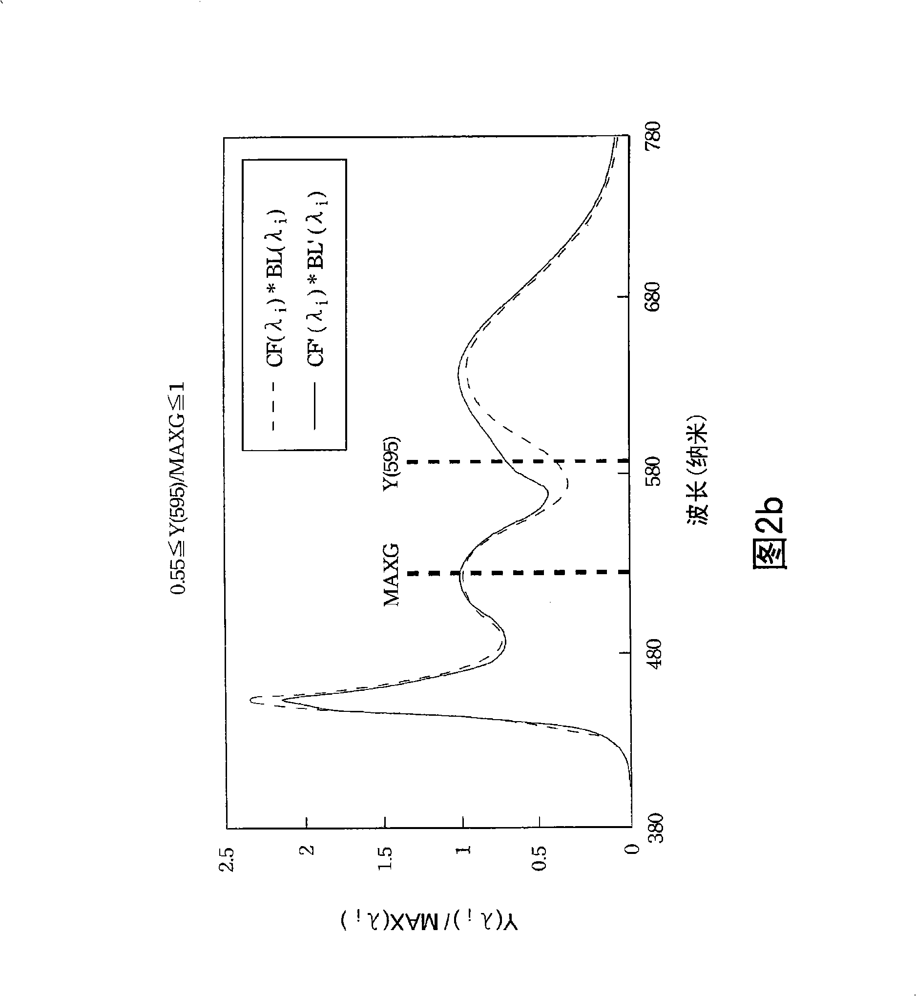
[0048] In this embodiment, the emission spectrum BL(λi) of the white light-emitting diode is between 430 nanometers (nm) and 470 nanometers (nm), 490 nanometers (nm) and 570 nanometers (nm) and 600 nanometers (nm) at wavelength λi. It has a relatively large brightness peak between nanometers (nm) and 680 nanometers (nm); wavelength λ1 can be 595 nanometers; wavelength λ2 can range between 490 nanometers (nm) and 570 nanometers (nm) (green in the light band). At this time, the emission spectrum BL(λi) and the transmission spectrum CF(λi) satisfy the following specific relationship:
[0049] Y(λ1)=CF(λ1)×BL(λ1);
[0050] MAX(λ2)=MAX[CF(λ2)×BL(λ2)];
[0051] 0.55≤Y(λ1) / MAX(λ2)≤1;
[0052] That is, the product Y(λ1) of the transmission spectrum CF(λ1) and the emission spectrum BL(λ1) at a wavelength λ1 of 595 nanometers (nm), that is, Y(595), and the transmission spectrum CF(λ2) and emission The maximum value of the product MAX(λ2) of the spectrum BL(λ2) when the wavelength λ2...
no. 3 example
[0056] In this embodiment, when the white balance color temperature range of the display device is between 5,000K and 8,500K; Between, between 490 nanometers (nm) and 570 nanometers (nm), and between 600 nanometers (nm) and 680 nanometers (nm), there is a relatively large brightness peak; the wavelength λ1 can be 595 nanometers (nm); the wavelength The range of λ2 may be between 430 nanometers (nm) and 470 nanometers (nm) (in the blue light band). At this time, the emission spectrum BL(λi) and the transmission spectrum CF(λi) satisfy the following specific relationship:
[0057] Y(λ1)=CF(λ1)×BL(λ1);
[0058] MAX(λ2)=MAX[CF(λ2)×BL(λ2)];
[0059] 0.25≤Y(λ1) / MAX(λ2)≤1;
[0060] That is, the product Y(λ1) of the transmission spectrum CF(λ1) and the emission spectrum BL(λ1) at a wavelength λ1 of 595 nanometers (nm), that is, Y(595), and the transmission spectrum CF(λ2) and emission The maximum value of the product MAX(λ2) of the spectrum BL(λ2) when the wavelength λ2 is between...
PUM
| Property | Measurement | Unit |
|---|---|---|
| wavelength | aaaaa | aaaaa |
| wavelength | aaaaa | aaaaa |
| wavelength | aaaaa | aaaaa |
Abstract
Description
Claims
Application Information
 - R&D
- Intellectual Property
- Life Sciences
- Materials
- Tech Scout
- Unparalleled Data Quality
- Higher Quality Content
- 60% Fewer Hallucinations
Browse by: Latest US Patents, China's latest patents, Technical Efficacy Thesaurus, Application Domain, Technology Topic, Popular Technical Reports.
© 2025 PatSnap. All rights reserved.Legal|Privacy policy|Modern Slavery Act Transparency Statement|Sitemap|About US| Contact US: help@patsnap.com


