Air cooling 350MW turbine generator

A steam turbine generator, air cooling technology, applied in the direction of cooling/ventilation devices, electromechanical devices, electrical components, etc., can solve the problems of ineffective cooling, ineffective cooling of rotor windings, temperature rise of rotor windings, etc., to achieve unit operation Safe and reliable, the axial temperature is basically uniform, and the effect of solving local overheating

Active Publication Date: 2010-08-25
NANJING TURBINE & ELECTRIC MASCH (GRP) CO LTD
View PDF0 Cites 0 Cited by
  • Summary
  • Abstract
  • Description
  • Claims
  • Application Information

AI Technical Summary

Problems solved by technology

Since one air outlet area corresponds to the middle section of the stator, neither the stator nor the middle section of the rotor can be effectively cooled; this problem is especially serious when the power of the turbogenerator increases
In addition, when the power increases, the temperature of the rotor winding rises, and the existing air path still cannot effectively cool the rotor winding

Method used


Image

  • Air cooling 350MW turbine generator
  • Air cooling 350MW turbine generator
  • Air cooling 350MW turbine generator

Examples


Embodiment Construction

[0022] specific implementation plan

[0023] The present invention will be described in further detail below in conjunction with the accompanying drawings and specific embodiments.

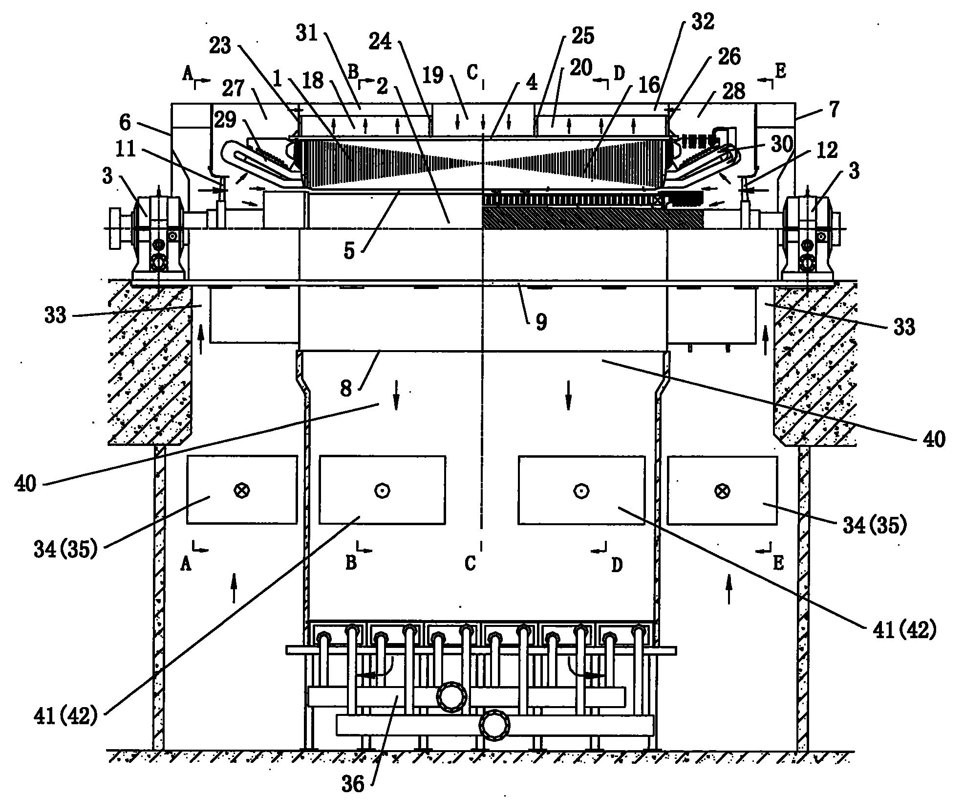
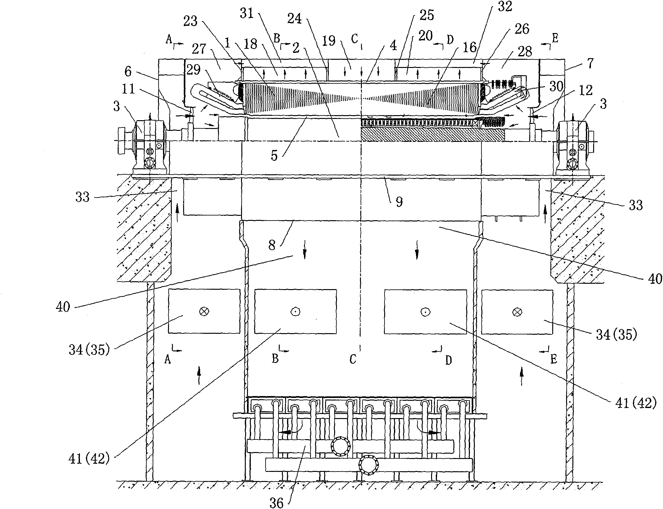
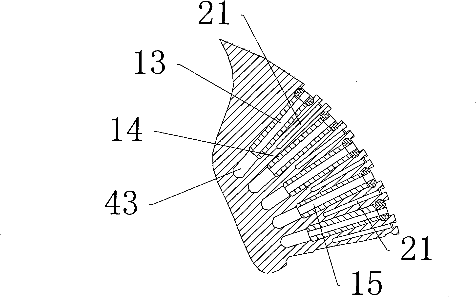
[0024] Referring to the air-cooled 350MW turbogenerator shown in Figure 1-7, both ends of the rotor 2 penetrating into the stator 1 are rotatably supported on the bearing 3, and the stator is set in the frame 4; there is a circumferential air gap between the stator and the rotor 5; front end cover 6, rear end cover 7 are arranged at the two ends of support, and air outlet bucket (bottom cover) 8 is arranged at the support bottom, and base plate 9 is arranged at support bottom both sides. The windshield 10 is arranged on the left and right sides of the base and connects with the bottom plate. Both ends of the rotor are provided with a front axial flow fan 11 and a rear axial flow fan 12. The rotor is provided with a wire slot 13 along the axial direction, and a wire slot 43 is opened along the axi...


PUM


Abstract

The invention provides a 350MW air cooling turbonator, the cooling system of which meets the requirements of a complete machine; the running of the turbonator is reliable, therefore, the turbonator solves the problems of rotor winding and temperature rise of the interlude of the rotor. The rotor is opened with an inserting winding air channel which is communicated with the bottom of an inserting winding groove; the rotor winding is opened with an air channel of the inserting winding groove, which is communicated with the inserting winding air channel and an air gap; the rotor among the inserting winding grooves is opened with a ventilating slot; five generating areas are formed axially along the rotor; the wind blown out from front and rear inlet air areas are divided into four paths; a first path wind is inlet from a ventilation duct to a middle inlet air area and is inlet to the air gap through a radial air duct; a second path wind is inlet to the air gap; the third path wind is inlet to the air gap through the inserting winding air channel and the air channel of the inserting winding groove; and a fourth path wind is inlet into the ventilating slot and then is inlet into the air gap radially along the rotor; the wind entering the air gap is inlet into front and rear outlet air areas by the radial air duct; the front and rear outlet air areas are communicated with an inlet of an air cooler, and the outlet of the air cooler is communicated with the front and rear inlet air areas.

Description

technical field [0001] The utility model relates to an air cooling steam turbine generator. technical background [0002] The birth of the motor has a history of more than 100 years. At the end of the 19th century, Europe began to produce small turbogenerators. my country's turbo-generator manufacturing started relatively late. In 1954, the first domestic air-cooled turbo-generator was successfully manufactured with a capacity of 6MW. In 1958, a 25MW turbo generator was manufactured successfully. [0003] Before the end of the 1930s, the turbogenerator was basically in a single air cooling stage. From a historical point of view, the development trend of turbogenerators is to increase the capacity of a single unit. The cooling effect required by large turbogenerators due to their good economy exceeds what air-cooling technology can provide, so people will inevitably focus on seeking a medium with a higher cooling level. The cooling media used by turbo generators in the wo...

Claims


Application Information

Patent Timeline
Patent Type & Authority Patents(China)
IPC IPC(8): H02K1/20H02K1/32H02K5/20H02K9/06
Inventor 姜兴林张文武周华翔杨俊东郭阳张木兰蔡吟
Owner NANJING TURBINE & ELECTRIC MASCH (GRP) CO LTD
Why Eureka
Try Eureka