Motor cooling structure and motor

A motor cooling and cooling pipe technology, applied in the direction of cooling/ventilation device, magnetic circuit shape/style/structure, electromechanical device, etc., can solve problems such as poor cooling and heat dissipation effect, improve efficiency and solve the effect of temperature rise

Active Publication Date: 2021-10-12
DUNSHI MAGNETIC ENERGY TECH
View PDF12 Cites 0 Cited by
  • Summary
  • Abstract
  • Description
  • Claims
  • Application Information

AI Technical Summary

Problems solved by technology

[0003] The purpose of the present invention is to provide a motor cooling structure, which aims to solve or at least improve to a certain extent the technical problem of poor cooling and heat dissipation effect of the existing motor stator

Method used


Image

  • Motor cooling structure and motor
  • Motor cooling structure and motor
  • Motor cooling structure and motor

Examples


Embodiment Construction

[0031] In order to make the technical problems, technical solutions and beneficial effects to be solved by the present invention clearer, the present invention will be further described in detail below in conjunction with the accompanying drawings and embodiments. It should be understood that the specific embodiments described here are only used to explain the present invention, not to limit the present invention.

[0032] It should be noted that the terms "length", "width", "height", "thickness", "top", "bottom", "front", "back", "left", "right", "vertical" , "horizontal", "top", "bottom", "inner", "outer", "head", "tail" and other indicated orientations or positional relationships are based on the orientations or positional relationships shown in the drawings, and are only for It is convenient to describe the present invention and simplify the description, but does not indicate or imply that the device or element referred to must have a specific orientation, be constructed a...


PUM


Abstract

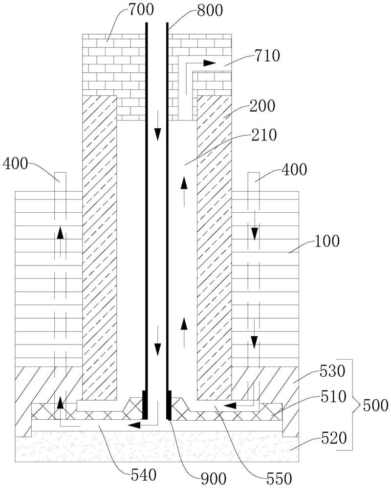
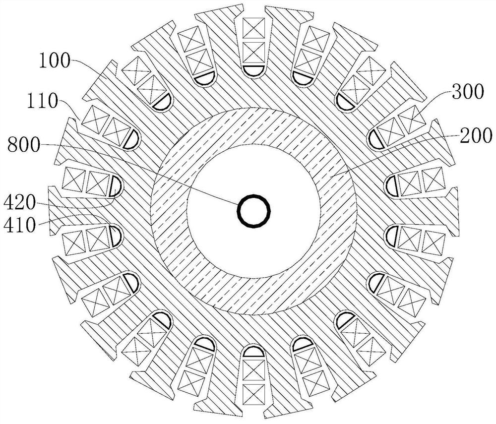
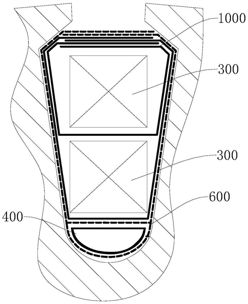
The invention is applicable to the technical field of motor equipment, and provides a motor cooling structure and a motor. The cooling structure of the motor includes stator core, stator winding, central shaft, liquid inlet pipeline, liquid outlet pipeline, manifold assembly and cooling pipe. The central shaft is provided with a central shaft hole, and the central shaft has a first end and a second end along its axial direction. The manifold body assembly is adjacent to the second end and connected with the stator core or the central shaft. It is configured with a first chamber and a second chamber. Pass. There are several cooling pipes, and each cooling pipe passes through at least one iron core slot. The motor cooling structure provided by the present invention is provided with a liquid inlet pipeline, a first chamber, a cooling pipe, a second chamber and a liquid outlet pipeline for the cooling liquid generated by the external cooling liquid circuit to pass sequentially, and through the The cooling pipes in the core groove are oriented to directly cool the stator core and the stator winding, which solves the problem of the temperature rise of the motor stator caused by the winding.

Description

technical field [0001] The invention belongs to the technical field of motor equipment, and more specifically relates to a motor cooling structure and a motor. Background technique [0002] The cooling system of traditional motors mostly adopts fan cooling and airflow cooling. The applicant found that the principle of this type of cooling system is to exchange heat with the external airflow, but the airflow can only circulate between the stator and rotor air gaps, and cannot directly act on the motor windings. And inside the iron core, because the winding is buried in the iron core slot and wrapped with multiple layers of insulating material, the heat dissipation effect is poor, which is not conducive to the long-term and high-frequency operation of the motor. Contents of the invention [0003] The purpose of the present invention is to provide a motor cooling structure, aiming to solve or at least improve to a certain extent the technical problem of poor cooling and heat ...

Claims


Application Information

Patent Timeline
Patent Type & Authority Patents(China)
IPC IPC(8): H02K1/20H02K5/20H02K9/197
CPCH02K1/20H02K5/20H02K9/197
Inventor 张令伟李胜飞刘凯飞岳川陈鹰唐英伟张广合焦志青郑金才
Owner DUNSHI MAGNETIC ENERGY TECH
Why Eureka
Try Eureka