Permanent magnet traction motor

A traction motor and permanent magnet technology, applied in electromechanical devices, electrical components, electric components, etc., can solve problems such as difficulty in meeting the cooling requirements of high power density motors, impossibility of rotor cooling, demagnetization of permanent magnet materials, etc.

Pending Publication Date: 2021-12-28
CSR ZHUZHOU ELECTRIC CO LTD
View PDF0 Cites 0 Cited by
  • Summary
  • Abstract
  • Description
  • Claims
  • Application Information

AI Technical Summary

Problems solved by technology

[0002] In the motor design work, the temperature rise of the motor has always been a place that needs to be paid attention to. Once the internal temperature rise of the motor is too high, the life of the motor insulation will be greatly reduced, and the damage of the insulation material means that the motor is scrapped.
For permanent magnet motors, once the temperature rises too high, the permanent magnet material will und

Method used


Image

  • Permanent magnet traction motor
  • Permanent magnet traction motor

Examples


Embodiment Construction

[0039] The following will clearly and completely describe the technical solutions in the embodiments of the present invention with reference to the accompanying drawings in the embodiments of the present invention. Obviously, the described embodiments are only some, not all, embodiments of the present invention. Based on the embodiments of the present invention, all other embodiments obtained by persons of ordinary skill in the art without making creative efforts belong to the protection scope of the present invention.

[0040] The core of the present invention is to provide a permanent magnet traction motor with better cooling effect.

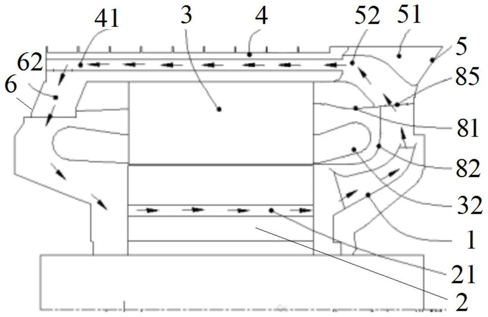
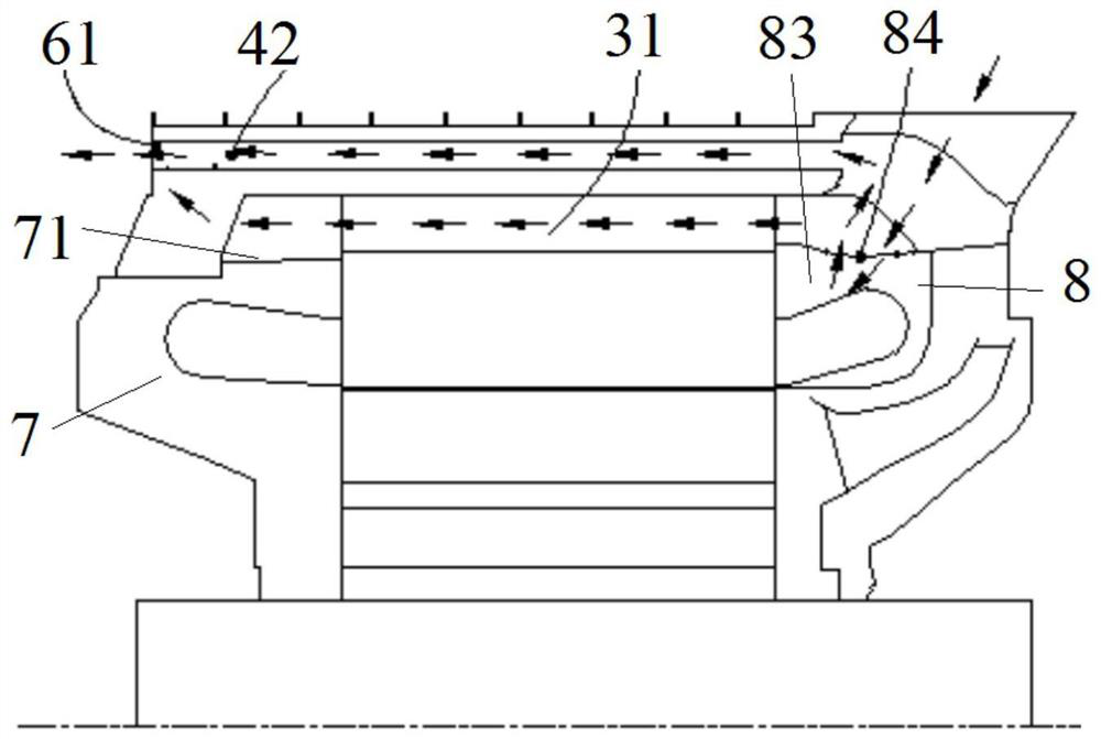
[0041] The specific embodiment one of the permanent magnet traction motor provided by the present invention is applied to passenger locomotives, please refer to figure 1 and figure 2 , including a rotor 2 and a stator 3 sleeved outside the rotor 2 to form a main body of the motor, and the rotor 2 rotates relative to the stator 3 . A first e...


PUM


Abstract

The invention discloses a permanent magnet traction motor which comprises a rotor, a stator, a first pressing ring, a second pressing ring and a fan, wherein the fan is located in a first axial space between the first pressing ring and a motor body in the axial direction, and a second axial space is formed between the second pressing ring and the motor body. A cooler is arranged on the peripheral face of the stator, and a cooler inner air duct and a cooler outer air duct are arranged on the cooler in an axial penetrating mode. The first pressing ring is provided with an air inlet, the second pressing ring is provided with an air outlet, and the air inlet, the cooler outer air duct and the air outlet are communicated to form an outer cooling air path. A rotor ventilation hole is formed in the rotor in an axial penetrating mode, the first end of the rotor ventilation hole is in butt joint communication with the first end of the cooler inner air duct through a first inner air duct, and the second end of the rotor ventilation hole is in butt joint communication with the second end of the cooler inner air duct through a second inner air duct to form an inner cooling air path. Under the driving of the fan, air circularly flows in the inner cooling air path. The motor is provided with internal and external cooling air paths, and the motor cooling effect is good.

Description

technical field [0001] The invention relates to the technical field of motors, in particular to a permanent magnet traction motor. Background technique [0002] In the motor design work, the temperature rise of the motor has always been a place that needs to be paid attention to. Once the internal temperature rise of the motor is too high, the life of the motor insulation will be greatly reduced, and the damage of the insulation material means that the motor is scrapped. For permanent magnet motors, once the temperature rises too high, the permanent magnet material will undergo irreversible demagnetization, which also means that the motor will be scrapped. [0003] In an existing permanent magnet traction motor, the cooling air enters from the outside of the motor and flows out of the motor through the axial ventilation holes of the stator, which cannot directly cool the rotor, and the cooling effect is limited, especially difficult to meet the cooling requirements of high p...

Claims


Application Information

Patent Timeline
IPC IPC(8): H02K1/20H02K1/32H02K5/20H02K9/19H02K9/04H02K9/06H02K9/18
CPCH02K1/20H02K1/32H02K5/207H02K9/19H02K9/04H02K9/06H02K9/18
Inventor 周茜茜崔可丰帆郑国丽王韬何维林陈庆波申政
Owner CSR ZHUZHOU ELECTRIC CO LTD
Why Eureka
Try Eureka