Two-way solar water heater

A technology for solar water heaters and water outlets, applied in solar thermal power generation, solar thermal devices, heating devices, etc., can solve the problems of waste, broken, broken, etc., and achieve the effect of low cost and simple structure

Inactive Publication Date: 2009-04-15
周明月
View PDF0 Cites 2 Cited by
  • Summary
  • Abstract
  • Description
  • Claims
  • Application Information

AI Technical Summary

Problems solved by technology

Since the heat collecting tube of the solar water heater is made of glass, it is easy to be broken under the action of ext

Method used


Image

  • Two-way solar water heater

Examples


Example Embodiment

[0008] Example 1:

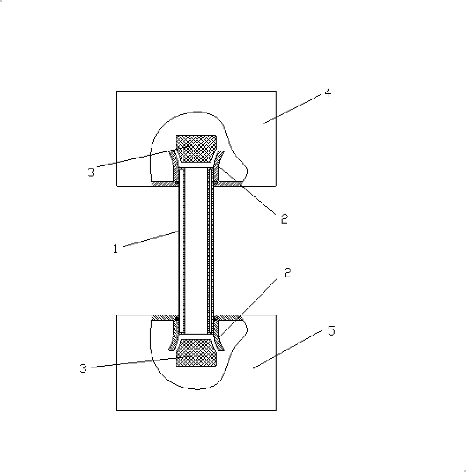
[0009] like figure 1 As shown, a double-pass solar water heater is provided with a straight-through heat collecting tube 1 with double openings, a water collecting tank 4 and a water supply tank 5 are respectively arranged at the upper and lower openings of the heat collecting tube 1, and the water outlets of the water collecting tank 4 and the water supply tank 5 Water outlet 3 is installed in 2 places respectively, the water outlet 2 is trumpet-shaped, the shape of water outlet 3 matches water outlet 2, and the material density of water outlet 3 is equal to the density of water, so there is no need to install other external objects in water outlet 3 to float.


PUM


Abstract

The invention discloses a bidirectional solar water heater which is provided with a straight heat collecting pipe (1) with dual openings; a water collecting tank (4) and a water supply tank (5) are respectively arranged at the upper opening and the lower opening of the heat collecting pipe (1). The bidirectional solar water heater is characterized in that the water through holes (2) of the water collecting tank (4) and the water supply tank (5) are respectively provided with a piston (3); the water through hole (2) is a horn shape; the shape of the piston (3) is matched with the shape of the water through hole (2); and the density of the material of the piston is equal to that of the water. The bidirectional solar water heater can quickly block the continuing loss of water in the water tank after the heat collecting pipe is broken, has simple structure, low cost and is convenient and practical.

Description

Technical field: [0001] The invention relates to a solar water heater used for preventing the phenomenon of water flow not stopping when a heat collecting tube is broken. Background technique: [0002] The solar water heater is a light-to-heat converter. The heat collecting tube is the core of the solar water heater. Its structure is like an elongated thermos bile, with a vacuum between the inner and outer layers. The outer surface of the inner glass tube is coated with a spectrally selective absorption coating using a special process to absorb solar radiation energy to the maximum. After being irradiated by sunlight, photons hit the coating, and the solar energy is converted into heat energy. The water absorbs heat from the coating, the temperature rises, the density decreases, and the hot water moves upward, while the cold water with a large specific gravity descends. The hot water is always located at the upper part. Circulation delivers hot water to the insulated water ...

Claims


Application Information

Patent Timeline
IPC IPC(8): F24J2/04F24J2/46
CPCY02E10/44
Inventor 周明月
Owner 周明月
Why Eureka
Try Eureka