Switchable antenna and electronic device

An electronic device and antenna technology, applied in the field of communication, can solve the problem that the antenna switching technology cannot be widely used, and achieve the effect of convenient switching

Active Publication Date: 2009-04-15
HUAWEI DEVICE CO LTD
View PDF0 Cites 15 Cited by
  • Summary
  • Abstract
  • Description
  • Claims
  • Application Information

AI Technical Summary

Problems solved by technology

[0005] The purpose of the present invention is to provide a switchable antenna and electronic equipment, which is used t

Method used


Image

  • Switchable antenna and electronic device
  • Switchable antenna and electronic device

Examples


Embodiment Construction

[0011] In order to make the purpose, technical features and implementation effects of the present invention clearer, the technical solution of the present invention will be described in detail below in conjunction with the accompanying drawings and specific embodiments. In the embodiment provided by the present invention, the insertion of the optional antenna itself is used as a trigger condition, and the switching between different antennas is realized simply and conveniently without interface control.

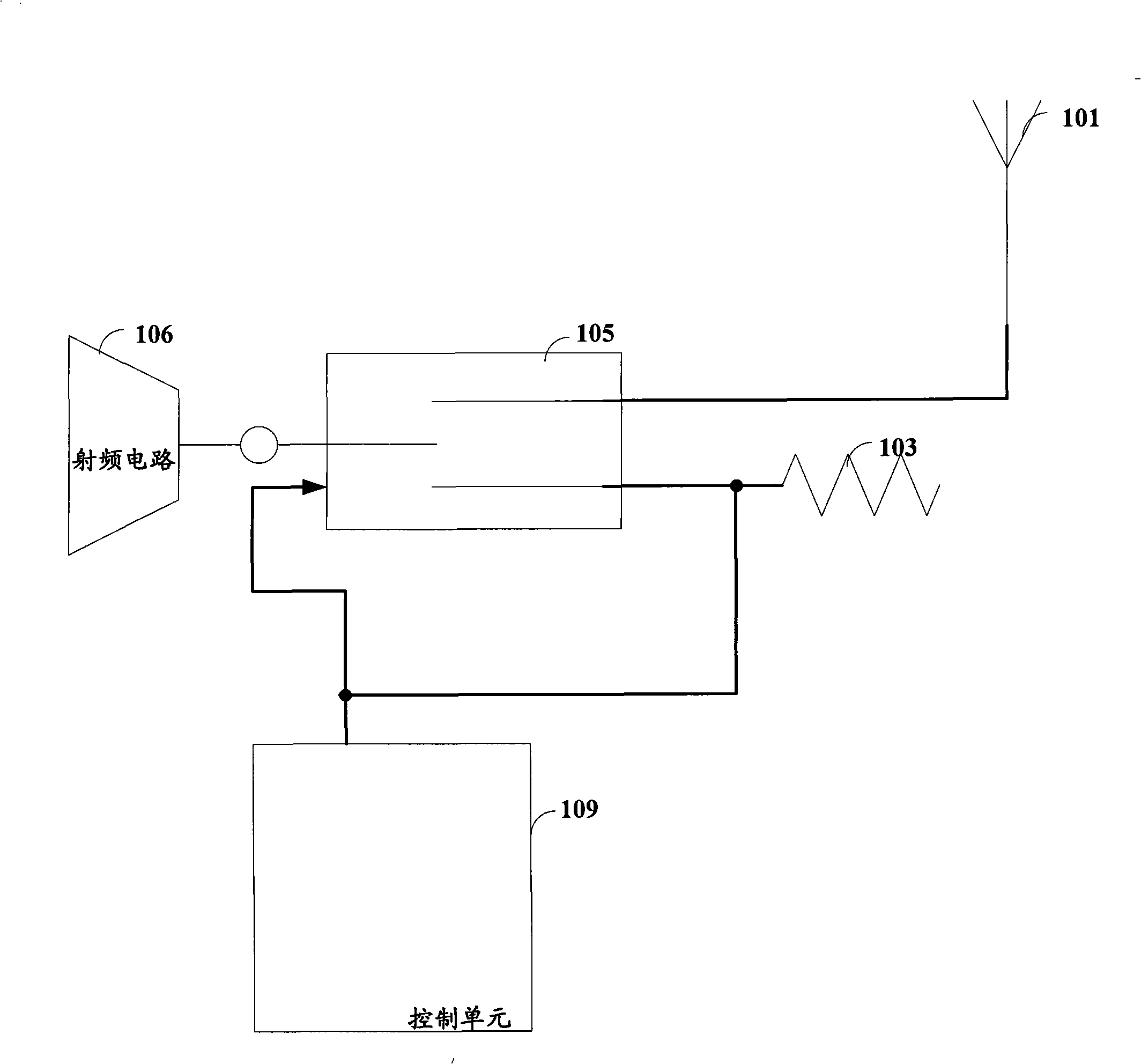
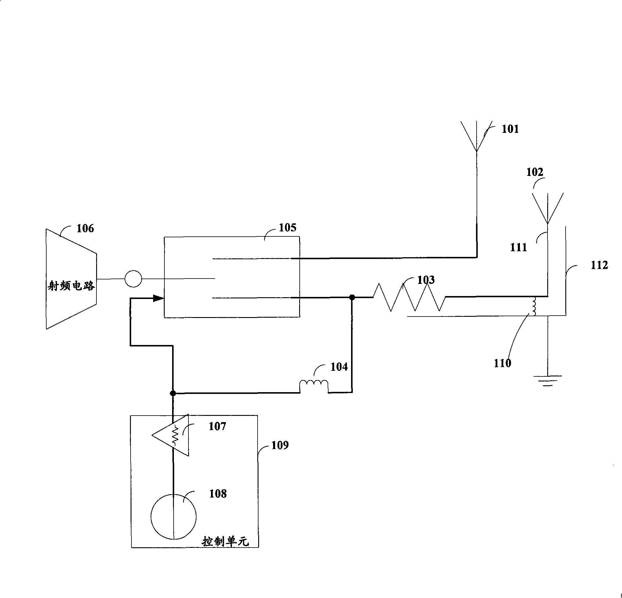
[0012] This embodiment provides a switchable antenna, such as figure 1 shown, including:

[0013] The antenna connector 103 is used to provide an interface with an optional antenna 102;

[0014] A radio frequency circuit 106, configured to generate and process radio frequency signals;

[0015] A radio frequency switch 105, the input terminal of which is connected to a control unit 109, is used to conduct with different transceiver paths according to different control levels...


PUM


Abstract

The invention provides a switchable antenna and electronic equipment, wherein, the switchable antenna comprises an antenna connector which provides an interface for being inserted with an adapting antenna; a radio-frequency circuit for generating and treating radio-frequency signals; a radio-frequency switch that is connected with different transceiving channels; and a default antenna used for receiving and sending the radio-frequency signals; wherein, the radio-frequency circuit, the radio-frequency switch and the default antenna form a default transceiving channel; the radio-frequency circuit and the radio-frequency switch form an adapting transceiving channel; the switchable antenna also comprises a control unit, when the antenna connector is inserted with the adapting antenna, second control level is output, and the radio-frequency switch connects the adapting transceiving channel to receive and send the radio-frequency signals according to the second control level; when the antenna connector is not inserted with the adapting antenna, first control level is output, and the radio-frequency switch connects the default transceiving channel to receive and send the radio-frequency signals according to the first control level. The embodiment of the invention has the advantage that software operation interface and other configuration are not needed in any application occasion, thus the user can conveniently realize the switch among different antennas.

Description

technical field [0001] The invention relates to communication technology, in particular to a switchable antenna and electronic equipment. Background technique [0002] Electronic devices are used in many scenarios, and have different requirements for antennas. For example, a small antenna is required for portability, and a large antenna is required for coverage and anti-interference in weak signal scenarios. [0003] In the existing technology, the same kind of adapter can be used to exchange antennas. Both antennas must be detachable; or occupy a pin of the main processing chip for logic control, and switch the antenna through the software background control switch. path; or when the optional antenna is inserted, the shrapnel is pressed down to disconnect the connection of the default antenna. [0004] In the process of realizing the present invention, the inventor found at least the following problems in the prior art: the specific connection method of the antenna is dema...

Claims


Application Information

Patent Timeline
IPC IPC(8): H04B1/38H04W88/02H04B1/40
Inventor 何卓彪隋艺周俭军
Owner HUAWEI DEVICE CO LTD
Why Eureka
Try Eureka