Cutting or etching device with tool provided with impeller for suction of dust

A technology of cutting tools and impellers, which is applied in the direction of manufacturing tools, metal processing equipment, metal processing machinery parts, etc., and can solve the problems of mechanical stress, inappropriate power, and environmental pollution of cutting heads, etc.

Inactive Publication Date: 2009-04-15
J.J.瓦格纳有限公司
View PDF0 Cites 2 Cited by
  • Summary
  • Abstract
  • Description
  • Claims
  • Application Information

AI Technical Summary

Problems solved by technology

[0012] Therefore, removal operations require frequent operators, create contamination to the surrounding environment, have significant limitations on productivity, and must be taken into account when calculating the average time required to manufacture each panel
[0013] Furthermore, particleboard material cannot be satisfactorily removed from the cut and etch process area during machining of the sheet metal, leaving the particleboard material at the corresponding portion of the tool cutting head and the sheet material facing the direction of forward movement of said tool cutting head relative to it between, which creates mechanical stress on the cutting head and jeopardizes the machining quality
[0014] On the other hand, increasing the power of the vacuum source may be inappropriate and rarely effective, as this only affects the installation and operating costs

Method used


Image

  • Cutting or etching device with tool provided with impeller for suction of dust
  • Cutting or etching device with tool provided with impeller for suction of dust
  • Cutting or etching device with tool provided with impeller for suction of dust

Examples


Embodiment Construction

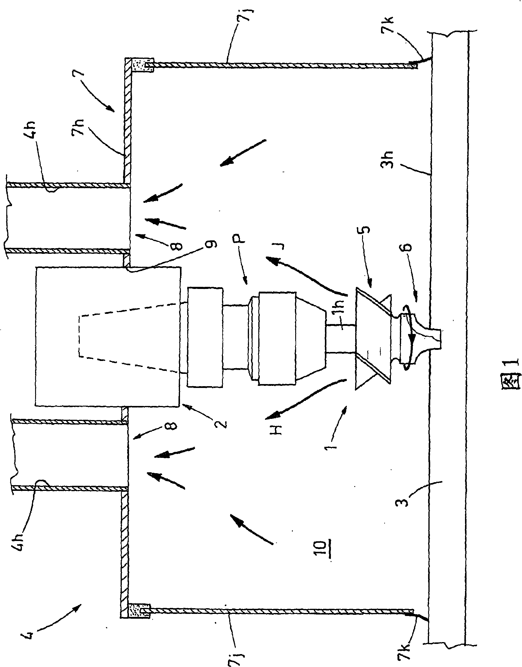
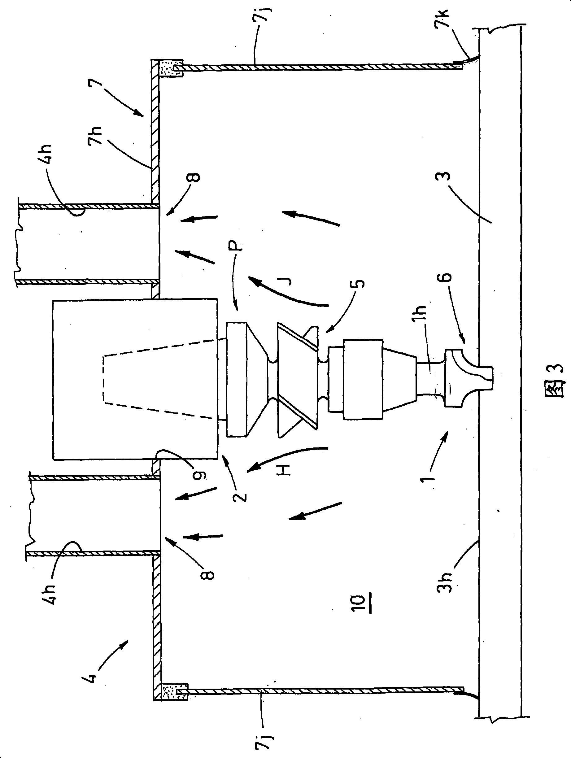
[0026] Attention is drawn to the drawings, reference numeral 1 designates a tool, which is driven in rotation by a spindle 2 connected to a drive mechanism of the machine tool, which is not shown because it is not relevant to the invention.

[0027] In particular, in the example shown, the tool holder element P is functionally interposed between the tool 1 and the spindle 2 ( FIG. 1 ).

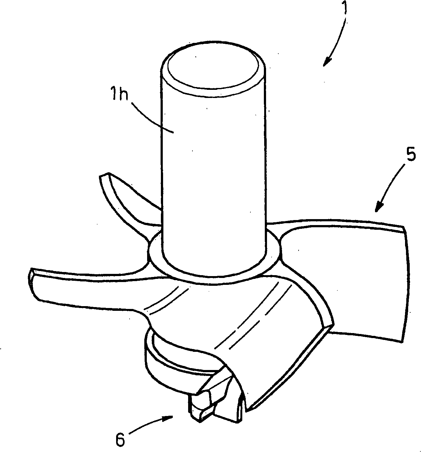
[0028] The cutter 1 comprises a shank 1h, the lower end of which forms a head 6 for cutting and / or etching objects, such as wood boards, and the shank 1h is equipped with an impeller 5 coaxial therewith, positioned above the head 6, and The key is fixed to the shank 1 h, or is integral with the knife 1 .

[0029] In the example shown, the impeller 5 has 4 blades arranged in two identical blade pairs (see figure 2 ), the two blade pairs are angularly equidistant.

[0030] Figure 1 shows a cover generally indicated at 7, formed by an upper part 7h, ie a cover plate, and side walls 7j, ending i...


PUM


Abstract

An operational group for etching and / or cutting articles, in particular panels, has a tool (1), driven into rotation by a mandrel (2) for cutting and / or etching the articles (3). Suction means (4) remove by suction fine and powdery wastes produced by the cutting and / or etching operations. An impeller (5), keyed onto the tool (1), removes, by suction, due to rotation of the tool (1), the fine and powdery wastes, produced by the cutting and / or etching operations, at least near the cutting head (6) of the tool (1), facilitating their subsequent suction by the suction means (4).

Description

technical field [0001] The present invention relates to machine tools for cutting and etching objects, especially wood panels. Background technique [0002] CNC machine tools are widely used to perform precision machining of wood panels such as cross cutting, hemming, punching and scaling in order to obtain a final product of improved quality. [0003] These operations are carried out by means of one or more tools driven in rotation by means of corresponding spindles, thus forming the operating tool head, and moving in a space within a defined operating area, where the rough workpiece to be machined is located Inside. [0004] Thus, each tool has 4 degrees of freedom and is governed by a drive mechanism that controls the movement of the tool and the cutting and / or etching operations according to selected patterns, the dimensional parameters of which are stored in the software of the machine tool. [0005] In this way, it is possible to obtain a series of productions of ite...

Claims


Application Information

Patent Timeline
Patent Type & Authority Applications(China)
IPC IPC(8): B23Q11/00
CPCB23Q11/0046Y10T408/44
Inventor A·科莱洛里
Owner J.J.瓦格纳有限公司
Why Eureka
Try Eureka