Aircraft component

一种飞机构件、飞机结构的技术,应用在飞机零件、机翼、机身框架等方向,能够解决危及机翼结构整体性等问题

Inactive Publication Date: 2009-04-15
AIRBUS OPERATIONS LTD
View PDF1 Cites 3 Cited by
  • Summary
  • Abstract
  • Description
  • Claims
  • Application Information

AI Technical Summary

Problems solved by technology

This causes excessive loads to be transferred to the adjacent wing feet, which jeopardizes the structural integrity of the wing

Method used


Image

  • Aircraft component
  • Aircraft component
  • Aircraft component

Examples


Embodiment Construction

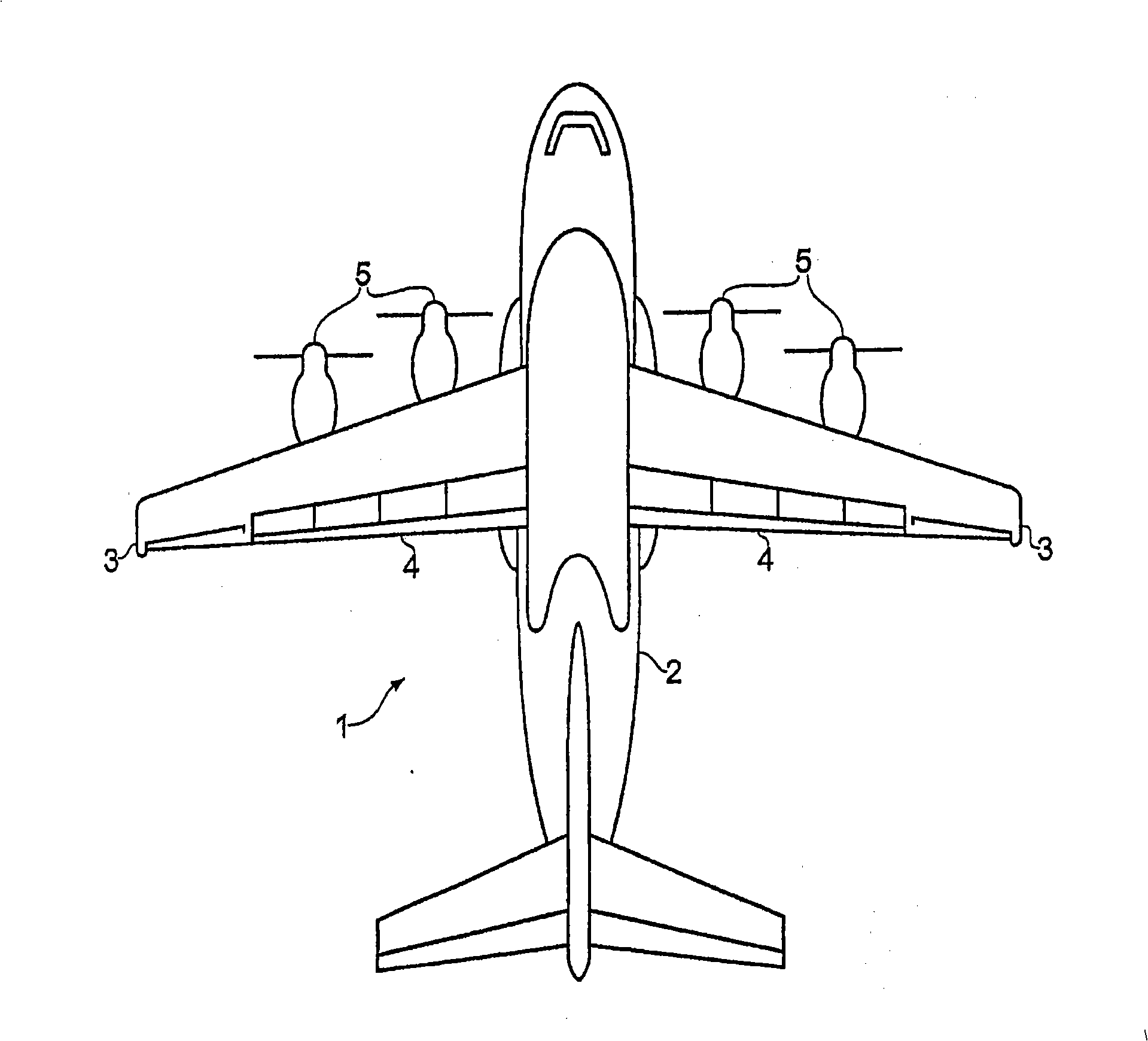
[0032] figure 1 An aircraft 1 is shown having a fuselage 2 and a pair of wings each having a wingtip 3 . Each wing has a pair of spars (not shown) mounted to the fuselage and extending spanwise. 24 ribs (not shown) extend chordwise. Flaps 4 are mounted at the trailing edge of each wing. The flap is carried by four flap attachments (not shown), each attached to a respective rib. Each wing carries a pair of engines 5, and each engine is connected to a corresponding rib by a support structure (not shown).

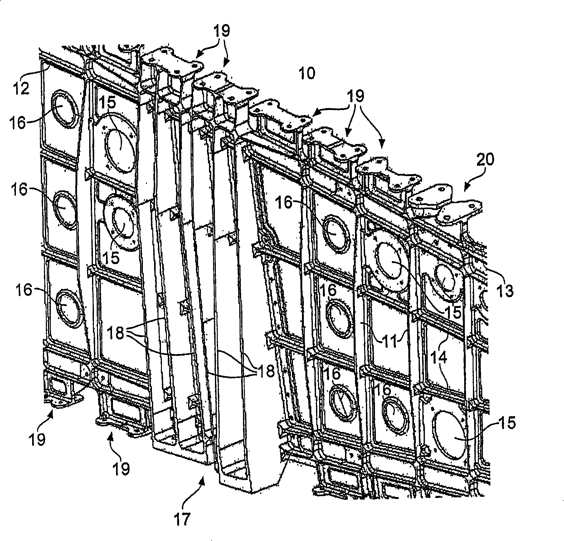
[0033] figure 2 The machined face of one of the ribs 10 is shown, with the leading and trailing edges of the rib omitted. Rib 10 is machined from billet aluminum to form a plurality of vertical ribs 11 , lower chord ridges 12 and upper chord ridges 13 , and horizontal ribs 14 . A fuel system bore 15 is formed to accommodate a fuel system tube. Holes 16 are formed in the intra-rib web to reduce the weight of the rib. The flap track attachment is formed with vertical ri...


PUM


Abstract

A method of manufacturing an aircraft component such as a wing rib. The method comprises: providing a body with two or more connectors (19, 20) arranged in a line on the body, each connector having an arm (35, 41) extending from the body, a first flange (23a) positioned on a first side of the line, and a second flange (23b) positioned on a second side of the line; and attaching a separate (30) connector to the body, the separate connector having an arm (35) extending from the body, a first flange positioned on a first side of the line and a second flange positioned on a second side of the line.

Description

technical field [0001] The invention relates to an aircraft component, a method of manufacturing an aircraft component, and a connection for transferring loads between a body and a cover of an aircraft component. The connection can be, for example, a wing foot for transferring loads between the wing skin and the rib. Background technique [0002] Wing feet for aircraft wing ribs are described in WO 01 / 76943. The wing feet have a pair of flanges each with a pair of pilot holes drilled in the final location of the final assembly holes for securing the wing skin. [0003] In the event of a wing foot failure, the entire load-bearing wing foot fails and the entire load is transferred to the adjacent wing foot. This can cause excessive loads to be transferred to the adjacent wing feet, which can jeopardize the structural integrity of the wing. Contents of the invention [0004] A first aspect of the invention provides a method of manufacturing an aircraft component, the metho...

Claims


Application Information

Patent Timeline
Patent Type & Authority Applications(China)
IPC IPC(8): B64C3/18B64C3/26B64C1/06B64C1/12
CPCB64C3/26B64C3/18
Inventor 安德鲁·罗伯特·芒迪
Owner AIRBUS OPERATIONS LTD
Why Eureka
Try Eureka