Dynamic damper and diesel engine where dynamic damper is mounted

A technology for dampers and diesel engines, applied in engine components, machines/engines, noise reduction devices, etc., can solve problems such as liquid leakage, unclear structure, unoptimized, etc., reduce vibration, improve safety and reliability, and handle easily Effect

Active Publication Date: 2011-03-23
MITSUI E&S MACHINERY CO LTD
View PDF4 Cites 0 Cited by
  • Summary
  • Abstract
  • Description
  • Claims
  • Application Information

AI Technical Summary

Problems solved by technology

For example, although the dynamic damper of Patent Document 2 is compact, a viscous body is accommodated in the casing, so there is a possibility of liquid leakage
In addition, the vibration damper device of Patent Document 3 describes that the interval between components can be changed in order to change the natural frequency, but its structure is unclear.
Furthermore, the method of manufacturing a dynamic damper in Patent Document 4 describes changing the outer tube (casing) in order to adjust the natural frequency. However, in a generator for power generation, etc., since the mounting position is limited, it is not preferable to increase the external dimensions.

Method used


Image

  • Dynamic damper and diesel engine where dynamic damper is mounted
  • Dynamic damper and diesel engine where dynamic damper is mounted
  • Dynamic damper and diesel engine where dynamic damper is mounted

Examples


no. 2 Embodiment approach

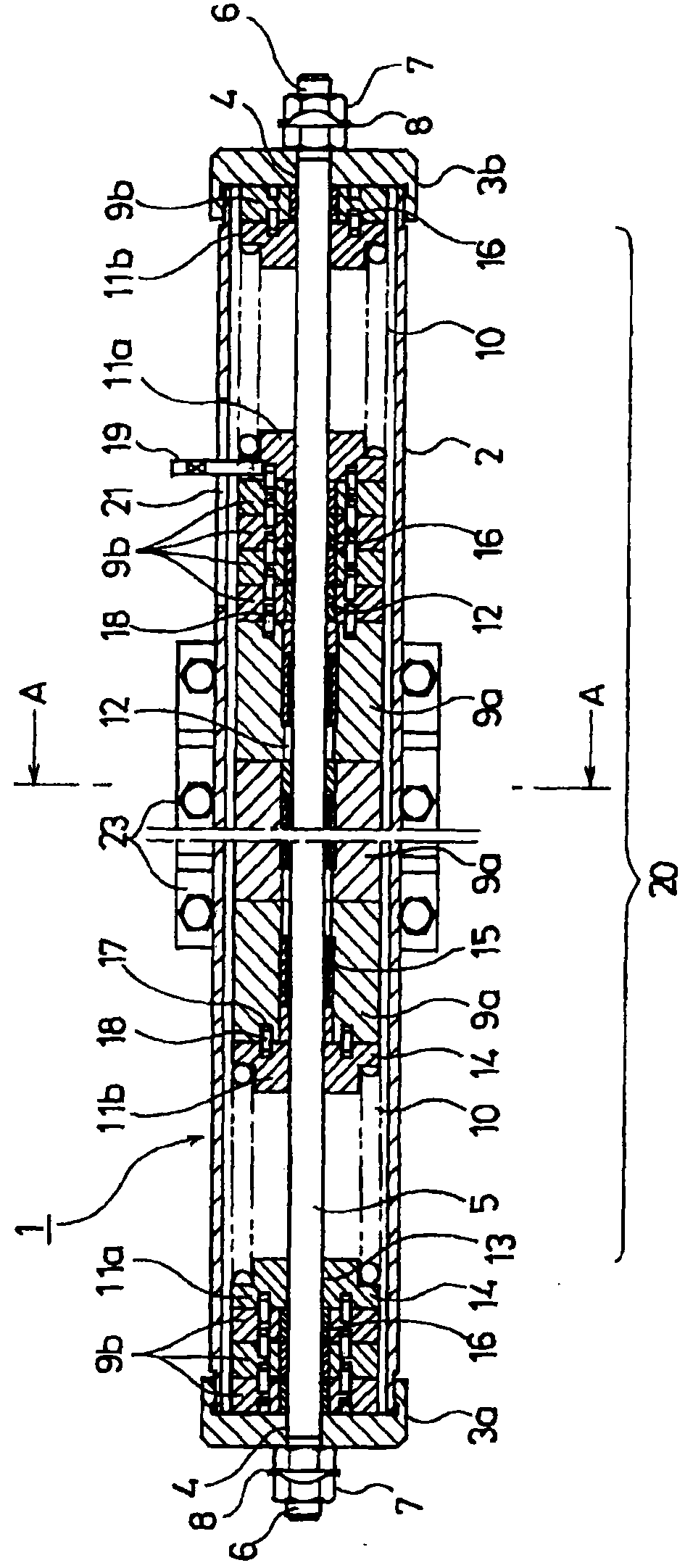
[0099] Next, a second embodiment will be described. However, the same reference numerals are assigned to the same components as those constituting the horizontal dynamic damper 1 described in the first embodiment, and detailed description thereof will be omitted.

[0100] The 2nd dynamic damper 1 as Figure 12 As shown, the guide rod support body 3 b is screwed onto the end of the housing 2 . That is, the female thread portion 42 provided inside the hem portion 28 of the guide rod support body 3 b is screwed to the male thread portion 41 provided on the outer peripheral surface of the housing 2 .

[0101] In addition, the threaded part 6a is provided only in the front end part of the guide rod outside the guide rod support body 3b, and the fastener 27 with the leg part or the hem part 26 is screwed to this threaded part 6a. And, the nut 7 as a fastener is screwed on the outside of the fastener 27 .

[0102] Furthermore, the protective cover 40 is screwed on the guide rod su...

no. 3 Embodiment approach

[0105] Next, a third embodiment will be described.

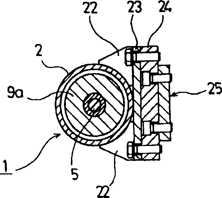
[0106] exist Figure 14 Among them, the reference numeral 30a is a large and low-speed two-cycle diesel engine for power generation equipment (for example, the rated speed is 100 to 200 rpm, and the output is about several thousand kW to 50,000 kW). A platform 210 for inspection of a grid (not shown). These inspection platforms 210 are vertically provided with longitudinal dynamic dampers (hereinafter simply referred to as dampers) 100 at positions where the vertical vibration is large, for example, at the ends of the inspection platforms 210 .

[0107] Damper 100 as Figure 15 As shown, it is a lengthwise structure. And, the damper main body 110 is composed of a cylindrical housing 112, a guide rod 113 provided in the housing 112, a vibration suppression weight 114 slidably provided on the guide rod 113, and a vibration suppression weight disposed on the vibration suppression weight. Coil-shaped springs 115, 116 on both...


PUM


Abstract

A dynamic damper capable of reducing vibration of a support where an exhaust collecting tube of a diesel engine is mounted. The dynamic damper has a tubular case (2), a guide bar (5) provided in the case (2), weights (9a) for vibration suppression slidably fitted on the guide bar (5), a pair of coil springs (10) arranged on both sides of the weights (9a), a pair of guide bar support bodies (3a, 3b) arranged at both ends of the case (2), a weight (9b) for adjusting natural vibration frequency, provided between each of the guide bar support bodies (3a, 3b) and each of the coil springs (10), fasteners (6) screwed to both ends of the guide bar (5), and support members (22, 23) arranged on side faces of the case (2).

Description

technical field [0001] The present invention relates to a dynamic damper and a diesel engine provided with the dynamic damper. Background technique [0002] In recent years, power generation equipment using a large low-speed two-cycle diesel engine with a rated speed of 100 to 200 rpm and an output of several thousand kW to 50,000 kW has attracted attention from the viewpoint of low fuel costs and easy maintenance and inspection. [0003] However, the exhaust manifold for diesel generators is installed above the exhaust side of the main engine (diesel engine), and vibrates horizontally larger than the main engine in synchronization with the vibration of the main engine. Therefore, damage to the support bracket supporting the exhaust manifold may occur. [0004] On the other hand, since the above-mentioned diesel engine requires a person to climb on top of the diesel engine for maintenance and inspection, a platform for inspection with a grid laid on the front side of the di...

Claims


Application Information

Patent Timeline
Patent Type & Authority Patents(China)
IPC IPC(8): F16F15/02F01N7/08F01N13/08
Inventor 梶原修平
Owner MITSUI E&S MACHINERY CO LTD
Why Eureka
Try Eureka