AI technical title is built by Patsnap AI team. It summarizes the technical point description of the patent document.
A technology of freezing device and decompression device, which is applied in refrigerators, refrigeration components, refrigeration and liquefaction, etc., to achieve the effect of improving decompression effect and high freezing capacity
Active Publication Date: 2011-11-09
SANYO ELECTRIC CO LTD
View PDF1 Cites 0 Cited by
Summary
Abstract
Description
Claims
Application Information
AI Technical Summary
This helps you quickly interpret patents by identifying the three key elements:
Problems solved by technology
Method used
Benefits of technology
Problems solved by technology
However, when the refrigerating device is sufficiently cooled, there is a problem that a large amount of liquefied surplus refrigerant is generated in the refrigerating device
Method used
Image
Click on the blue label to locate the original text in one second.
Reading with bidirectional positioning of images and text.
Examples
Embodiment 1
[0039] (1) Freezing device applicable to the present invention
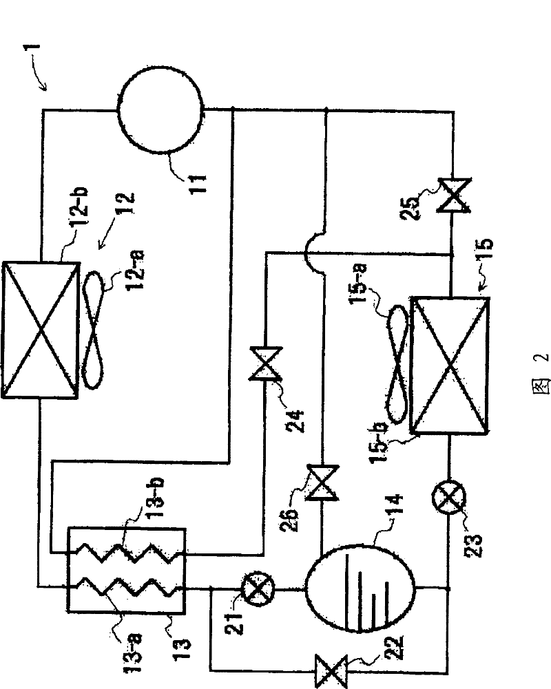
[0040] figure 2 It is a refrigerant circuit 1 of a refrigeration system to which an embodiment of the present invention is applied. In the drawings, reference numeral 11 denotes a compressor, 12 denotes a gas cooler, 13 denotes a cascade heat exchanger (internal heat exchanger), 14 denotes a liquid receiver, 15 denotes an evaporator, and 21 denotes a second expansion valve (reduction pressure device), 22, 24, 25 and 26 represent solenoid valves (on-off valves), and 23 represent the first expansion valve.
[0041] In addition, the compressor 11 is a single stage or a multi-stage compressor with two or more stages. Since the refrigerant is in a subcritical state on the low-pressure side of the compressor 11 and the output refrigerant is in a supercritical state, the entire refrigeration system is in a transition critical state. As a refrigerant having the above properties, carbon dioxide is used in this embodim...
Embodiment 2
[0070] Next, based on Figure 7 ~ Figure 11 Other embodiments of the present invention will be described in detail.
[0071] (5) Freezing device applicable to the present invention
[0072] Figure 7 It is the refrigerant circuit 1 of the refrigerating apparatus of another embodiment of the present invention to which it is applied. In the drawings, reference numeral 11 denotes a compressor, 12 denotes a gas cooler, 13 denotes a cascade heat exchanger (internal heat exchanger), 14 denotes a liquid receiver, 15 denotes an evaporator, and 21 denotes a second expansion valve (reduction pressure device), 22, 24, 25 and 26 represent solenoid valves (on-off valves), and 23 represent the first expansion valve.
[0073] The compressor 11 is a multi-stage compressor of two or more stages capable of sucking refrigerant not only from the low-pressure part but also from the intermediate-pressure part. Since the refrigerant is in a subcritical state on the low-pressure side of the compr...
PUM
Abstract
A freezing apparatus using such a coolant as will take a supercritical state when discharged from a compressor is troubled by a problem that the charge of the coolant has to be increased to quicken the cooling operation, because of shortage of the freezing power. Another problem is that an excess coolant is much produced in a coolant circuit when the freezing apparatus is sufficiently cooled. Provided is a coolant circuit, in which a compressor, a gas cooler, a first pressure reducing device and an evaporator are sequentially piped and connected in an annular shape. The coolant circuit comprises a second pressure reducing device and a liquid receiver between the gas cooler and the first pressure reducing device, and the liquid receiver and the suction port of the compressor are piped and connected. The opening degree of the second pressure reducing device is controlled according to the pressure difference between the discharge side pressure and the suction side pressure of the compressor, so that the circulation rate of the coolant can be adjusted by increasing the coolant circulation rate in case the freezing ability is short and by reserving the excess coolant in the liquid receiver in case the freezing ability is excessive.
Description
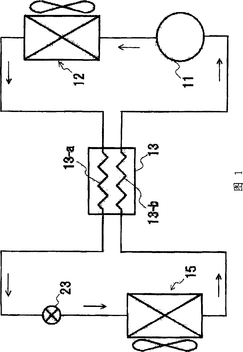
technical field [0001] The present invention relates to a refrigerating device having a refrigerant circuit in which a compressor, a gas cooler, a decompression device, an evaporator, etc. are connected by piping, and using carbon dioxide (CO 2 ) and other natural refrigerants. Background technique [0002] In the past, Freon-based refrigerants were used in refrigeration equipment, but due to the problems of Freon depleting the ozone layer and causing the global warming effect, its use began to be strictly limited. As an alternative refrigerant, CO 2 The development of refrigeration equipment for natural refrigerants such as natural refrigerants or hydrocarbons is underway. [0003] Among the above-mentioned natural refrigerants, refrigerants that are particularly expected as next-generation refrigerants are expected to be non-flammable, unlike flammable hydrocarbons or toxic ammonia, even though they have a low global warming coefficient. And it is non-toxic, so it is fri...
Claims
Application Information
Patent Timeline
Application Date:The date an application was filed.
Publication Date:The date a patent or application was officially published.
First Publication Date:The earliest publication date of a patent with the same application number.
Issue Date:Publication date of the patent grant document.
PCT Entry Date:The Entry date of PCT National Phase.
Estimated Expiry Date:The statutory expiry date of a patent right according to the Patent Law, and it is the longest term of protection that the patent right can achieve without the termination of the patent right due to other reasons(Term extension factor has been taken into account ).
Invalid Date:Actual expiry date is based on effective date or publication date of legal transaction data of invalid patent.

