Drawing device and drawing method

A drawing device and polygonal technology, applied in the field of surface or curve approximation technology, can solve the problems of slow drawing time, processing time, and polygon vertex deletion methods that are difficult to fully respond to, etc.

Inactive Publication Date: 2009-04-15
PANASONIC CORP
View PDF1 Cites 1 Cited by
  • Summary
  • Abstract
  • Description
  • Claims
  • Application Information

AI Technical Summary

Problems solved by technology

[0006] However, since the process of deleting vertices of polygons itself takes time, the conventional method of deleting vertices of polygons has a problem that the processing time cannot be reliably shortened in consideration of the overall drawing time.
[0007] That is, when the deletion processing of the polygon vertices has no effect (that is, when the vertices are deleted, the shape will change greatly, because this will cause a sense of incongruity, the deletion process is not performed) This part of the , takes unnecessary processing time and as a result slows down the overall render time
[0008] Moreover, in recent years, mobile phones and portable game consoles and other devices that do not necessarily have high processing performance are required to be able to express moving three-dimensional objects at a speed that does not feel uncomfortable. The deletion method is difficult to adequately correspond to

Method used


Image

  • Drawing device and drawing method
  • Drawing device and drawing method
  • Drawing device and drawing method

Examples


Embodiment 1

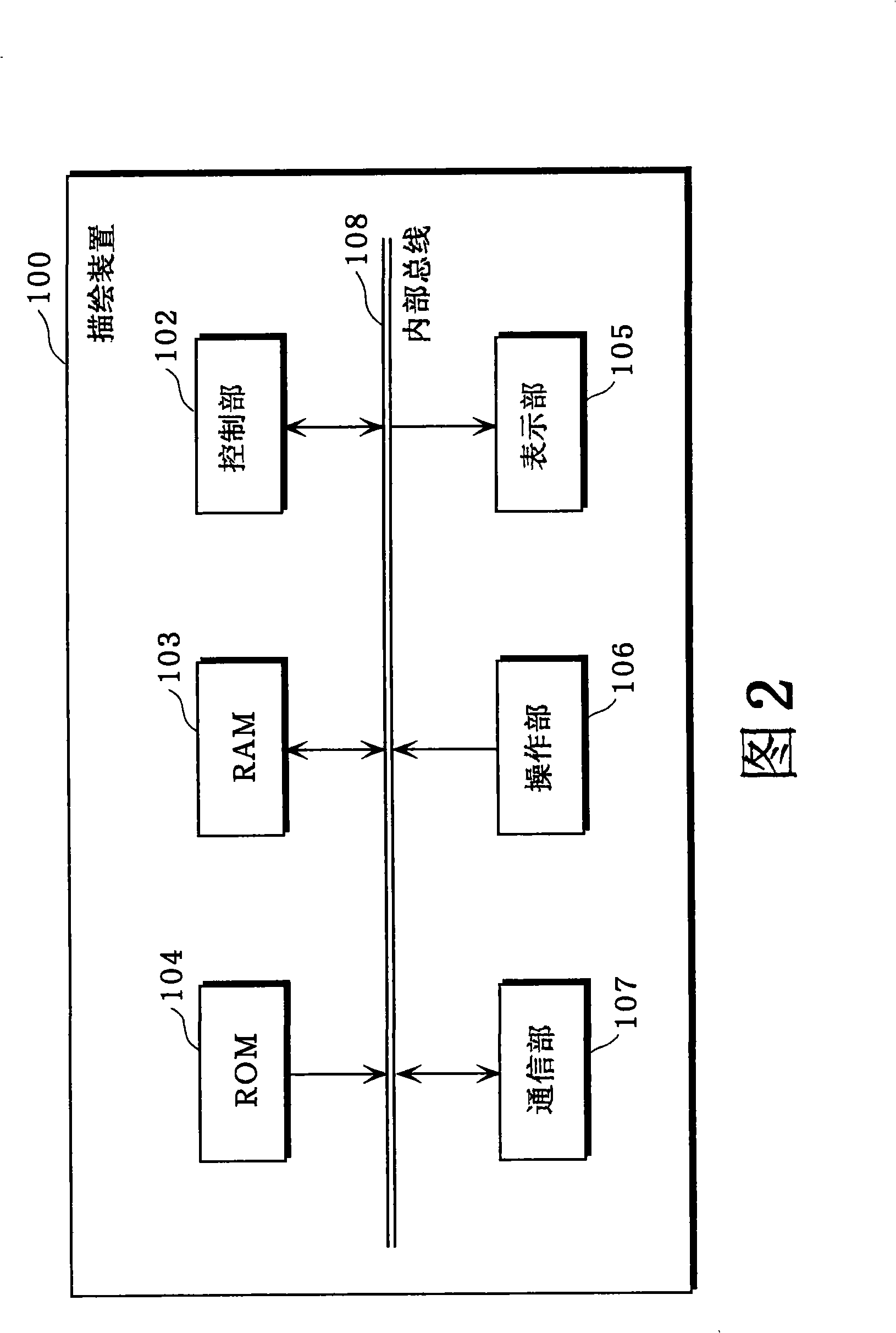
[0059] FIG. 2 shows a schematic configuration of the rendering device 100 according to this embodiment. The rendering device 100 according to this embodiment performs polygon simplification based on the three-dimensional position coordinate value, color value attached to the vertex, texture coordinate data, or normal vector included in the polygon as attribute data on each vertex. installation. In addition, the rendering method described below can be used for the rendering device 100 and the like. However, the rendering device 100 is a specific example for describing the rendering device according to the present invention, and is not limited to the rendering device 100 , and may be other electronic devices such as a mobile phone or a personal computer, for example.

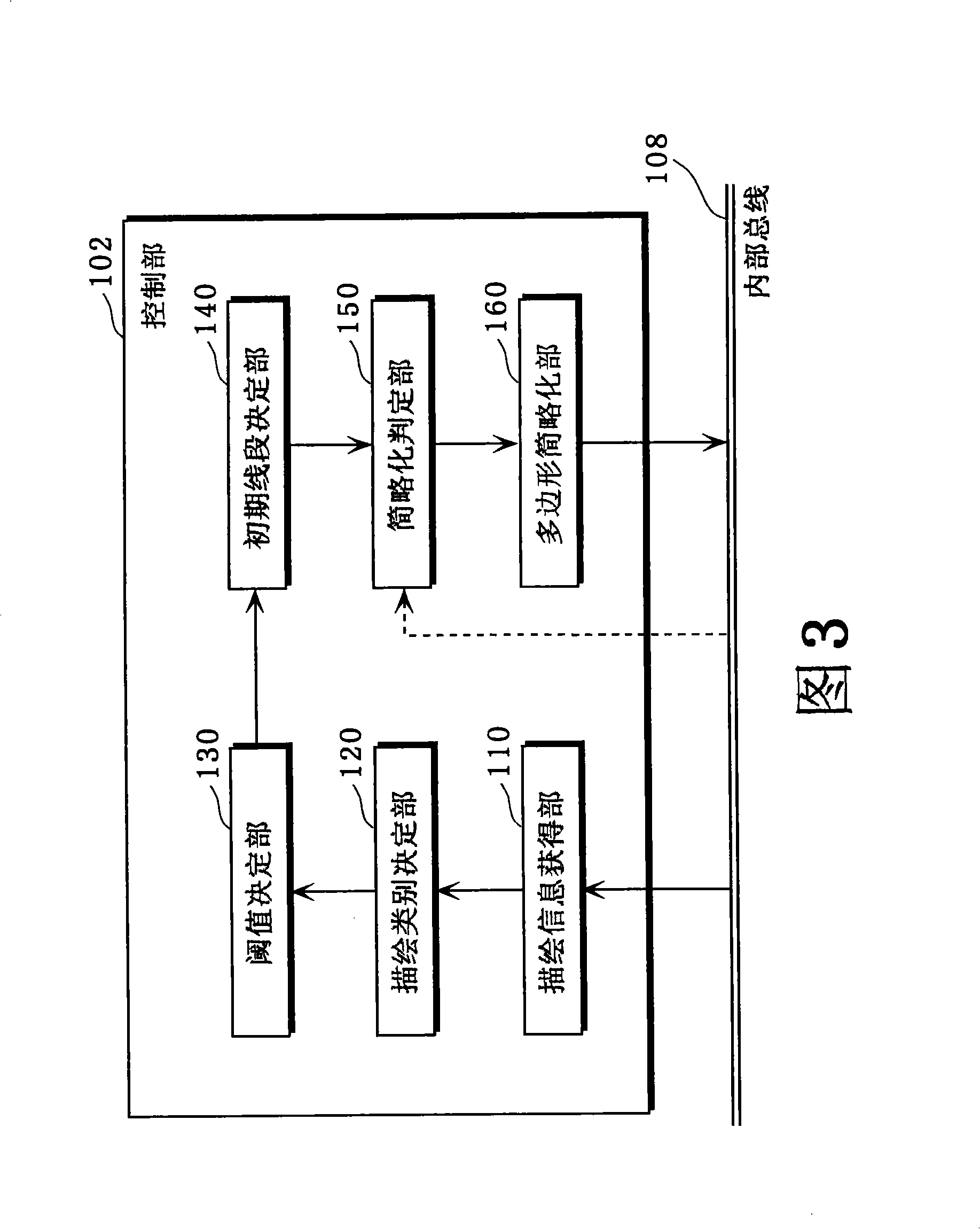
[0060] As shown in FIG. 2 , the main components of the rendering device 100 include a control unit 102 , a RAM 103 , a ROM 104 , a display unit 105 , an operation unit 106 , and a communication unit 107 . In add...

Embodiment 2

[0177] In the above-mentioned first embodiment, the embodiment of the polygon obtained by the drawing information obtaining unit 110 defined by "FAN type (fan type)" was described. The embodiment of polygon simplification after converting the polygon defined by "FAN type" into "FAN type" will be described.

[0178] In the rendering device according to the present embodiment, the rendering information obtaining unit 110 in the rendering device 100 according to the first embodiment also has a function of converting a polygon defined in the STRIP type into a FAN type. The other functional configurations are the same as those of the rendering device 100 according to the first embodiment described above.

[0179]FIG. 14 shows two forms when defining a polygon that is a polygon (hexagon in the case of FIG. 14 ). As shown in FIG. 14, a polygon defined with the STRIP type (STRIP type polygon) is defined in a zigzag manner from top to bottom (for example, according to the value of the...


PUM


Abstract

Intended is to make it possible to simplify a polygon in a device having a processing ability not necessarily high, and to shorten a total processing time period in a CG (Computer Graphics). Provided is a drawing device comprising a reference information acquiring unit for acquiring reference information containing the kind of a drawing operation usable in the CG and the characteristic of the shape of the polygon, a drawing information acquiring unit for acquiring drawing information containing the information indicating the kind of the drawing operation to be used in the actual CG and the information indicating the shape of the polygon, simplification determining means for determining whether or not the kind of the drawing operation indicated by the drawing information and the shape of the polygon satisfy the reference indicated by the reference information, polygon simplifying means for simplifying the polygon, in case the satisfaction of the reference is determined by the simplification determining means, by reducing the apexes constituting the polygon, and drawing means for executing the CG with the polygon having its apexes reduced.

Description

technical field [0001] The present invention relates to computer graphics technology in computers, various information devices, mobile phones, game machines, etc., and especially relates to the approximation technology of curved surfaces or curves. Background technique [0002] In three-dimensional computer graphics, three-dimensional curved surfaces and the like are approximated and drawn by polygonal polygons and the like. [0003] Conventional polygon-by-polygon drawing processing requires a huge amount of processing time, so a technique for simplifying the drawing process by reducing vertices of polygons is disclosed (for example, refer to Patent Document 1). [0004] figure 1 is a block diagram of the aforementioned conventional texture data generation device. In conventional texture data generation devices, the number of polygons can be reduced by the polygon reduction unit 1 . Furthermore, the vertex position calculation unit 2 calculates which position of the new ...

Claims


Application Information

Patent Timeline
Patent Type & Authority Applications(China)
IPC IPC(8): G06T15/00
CPCG06T15/00G06T17/20
Inventor 岛崎贵正深见幸靖白井靖久
Owner PANASONIC CORP
Why Eureka
Try Eureka