Stamping cutting die

A technology of punching knife and in-mold injection, applied in the field of punching knife die

Inactive Publication Date: 2009-04-22
KAOTAI TECH
View PDF0 Cites 11 Cited by
  • Summary
  • Abstract
  • Description
  • Claims
  • Application Information

AI Technical Summary

Problems solved by technology

[0006] The purpose of the present invention is to overcome the defects existing in the existing stamping dies and provide a stamping die with a new structure. The technical problem to be solved is to reduce the contact area with the film during stamping, thereby enabling the The stamped and cut film is not easy to produce white edges, which is very suitable for practical use

Method used


Image

  • Stamping cutting die
  • Stamping cutting die
  • Stamping cutting die

Examples


Embodiment Construction

[0022] In order to further explain the technical means and effects of the present invention to achieve the intended purpose of the invention, the specific implementation, structure, characteristics and effects of the stamping die proposed according to the present invention will be described below in conjunction with the accompanying drawings and preferred embodiments. Details are as follows.

[0023] The aforementioned and other technical contents, features and effects of the present invention will be clearly presented in the following detailed description of preferred embodiments with reference to the drawings. Through the description of the specific implementation mode, when the technical means and functions adopted by the present invention to achieve the predetermined purpose can be obtained a deeper and more specific understanding, but the accompanying drawings are only for reference and description, and are not used to explain the present invention be restricted.

[0024...


PUM


Abstract

The invention relates to a punching cutting die, which is assembled on a punching machine board and is used for cutting excess materials of a plastic or metal film which can be used for injection molding in a mold. The punching cutting die is provided with a punching cutter edge and a plurality of dentiform structures which are arranged along the punching cutter edge. The dentiform structures can be square, triangular or trapezoidal. The parts of the punching cutting die contacted with the film are designed into the arranged dentiform structures to reduce the contact area with the film in the process of punching so as to reduce the probability of white edge, and the film appearance can be free from being influenced.

Description

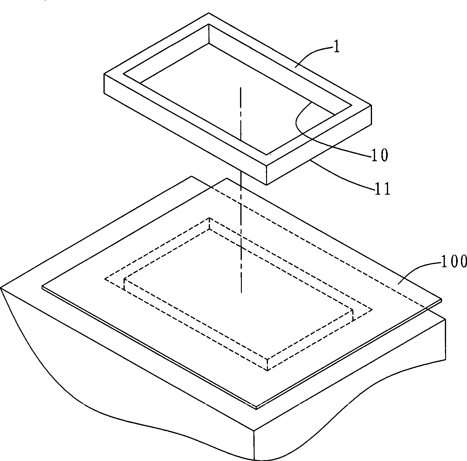
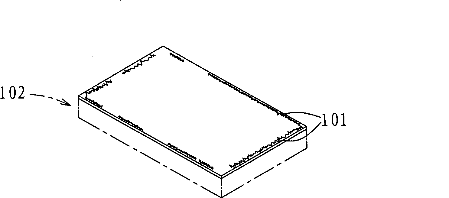
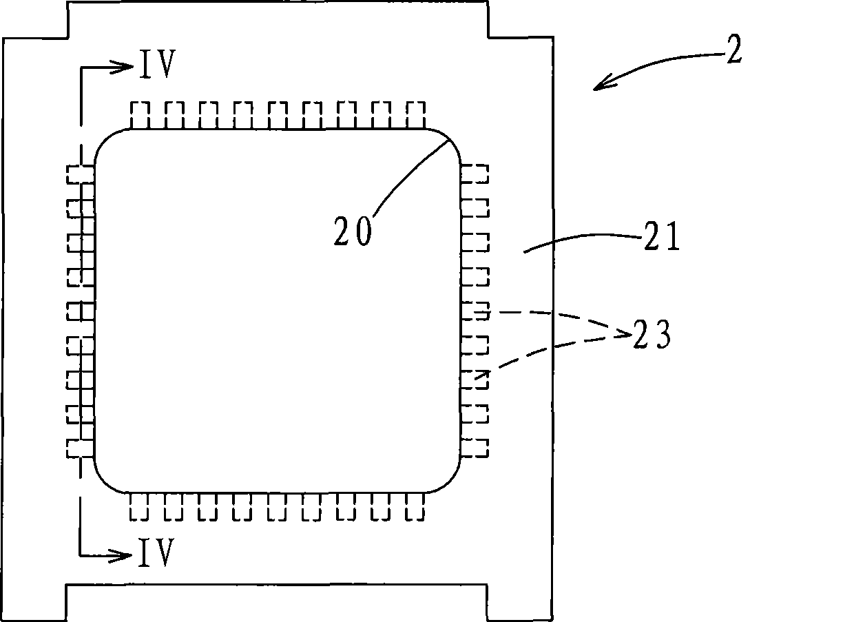
technical field [0001] The invention relates to a stamping knife die, in particular to a stamping knife die which can be installed on a stamping machine table for cutting the remaining material of a plastic or metal film to be injected into the mold. Background technique [0002] Before the known film used for in-mold injection molding is put into the injection molding mold, it is necessary to use a punching machine to remove the excess material around the film, and then put the film into the mold for injection molding. [0003] see figure 1 , figure 2 as shown, figure 1 It is a schematic diagram of the existing known film stamping process to remove the surrounding material, figure 2 so figure 1 Schematic diagram of existing known stamping dies that are easy to produce white edges on thin films. Such as figure 1 As shown, for example, take the stamping machine (not shown) equipped with a frame-shaped stamping die 1 as an example, when the film 100 is punched, the fil...

Claims


Application Information

Patent Timeline
Patent Type & Authority Applications(China)
IPC IPC(8): B26F1/44
Inventor 洪胜忠
Owner KAOTAI TECH
Why Eureka
Try Eureka