CD grain machine

A technology of embossing machine and rack, applied in the field of CD embossing processing equipment, can solve problems such as poor production quality

Active Publication Date: 2016-01-13
东莞市发斯特精密科技股份有限公司
View PDF7 Cites 6 Cited by
  • Summary
  • Abstract
  • Description
  • Claims
  • Application Information

AI Technical Summary

Problems solved by technology

[0006] The purpose of this invention is to provide an improved CD grain machine to solve the problem of poor production quality in the prior art

Method used


Image

  • CD grain machine
  • CD grain machine
  • CD grain machine

Examples


Embodiment Construction

[0028] In order to describe the technical content, structural features, achieved goals and effects of the present invention in detail, the following will be described in detail in conjunction with the embodiments and accompanying drawings.

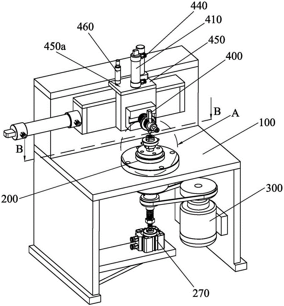
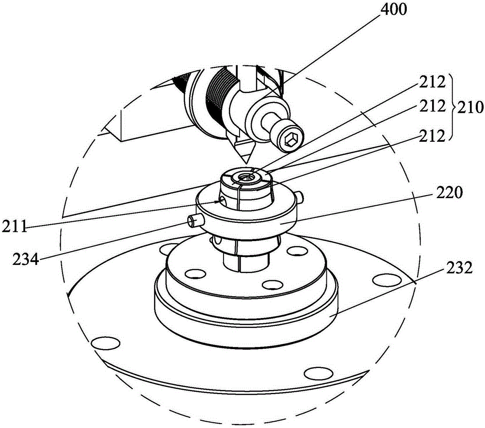
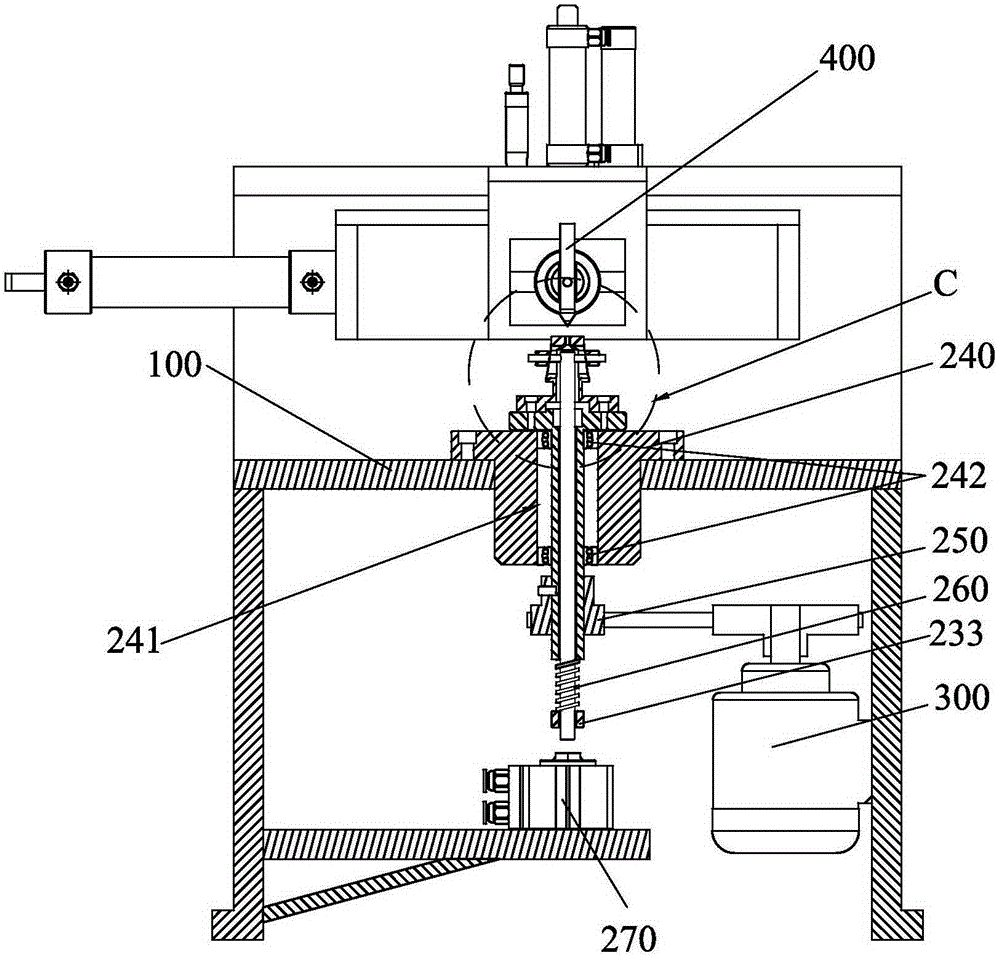
[0029] Such as figure 1 As shown, the CD graining machine provided by the present invention is used to process the CD grain of the workpiece, and it includes a frame 100, a clamping mechanism 200, a power device 300 for driving the clamping mechanism 200 to rotate at a high speed, and a drive pair clamping mechanism 200 The cutter shaft mechanism 400 for processing the CD pattern on the clamped workpiece. Wherein, the clamping mechanism 200 is rotatably connected to the frame 100, the power device 300 is fixedly connected to the frame 100, and the output end of the power device 300 drives the clamping mechanism 200 to rotate relative to the frame 100; One side of the clamping mechanism 200 is used to process the CD pattern on the workpiec...


PUM


Abstract

The invention discloses a CD grain machine which comprises a rack, a clamping mechanism, a power device for driving the clamping mechanism to rotate and a cutter shaft mechanism for driving CD grain machining on a workpiece. The clamping mechanism comprises a locating seat used for being fixedly connected to the rack and a pull rod rotationally connected to the locating seat. A clamping barrel and a clamping barrel sleeve used for locking the clamping barrel are arranged on the upper side of the pull rod. The cross section of the outer wall of the clamping barrel is round, and the outer wall of the clamping barrel is gradually increased downwards. The outer wall of the clamping barrel is sleeved with the clamping barrel sleeve, the pull rod is connected to the clamping barrel sleeve, and the clamping barrel sleeve has the motion tendency of clamping the clamping barrel downwards all the time. The cutter shaft mechanism comprises a feeding air cylinder, a locating plate connected to the output end of the feeding air cylinder, a machining cutter driven by the feeding air cylinder, a limiting datum plane and a buffer which is connected to the locating plate and located on one side of the limiting datum plane. When the machining cutter is driven by the feeding air cylinder to move towards the workpiece, the buffer is gradually close to the limiting datum plane and abuts against the limiting datum plane. According to the CD grain machine, the machining quality of the workpiece can be improved.

Description

technical field [0001] The invention relates to a machining equipment, in particular to a CD grain processing equipment. Background technique [0002] The CD pattern processing mainly uses the CD pattern processing equipment to suck the workpiece through the vacuum fixture, process the tool feed stroke and the cutting process stroke after the power is turned on. After the product is sucked tightly by the vacuum fixture, the processing button is started, and the feed cylinder drives the machining tool to feed the product to the processing surface. After the feed cuts into the surface of the workpiece, the horizontal feed cylinder pushes the processing tool for horizontal chip processing, so that the surface of the workpiece can obtain the CD pattern effect of gradually expanding radius. [0003] When using CD pattern processing equipment to make small hardware parts, the effect of vacuum suction and clamping method is not ideal during the operation process. The main reason i...

Claims


Application Information

Patent Timeline
Patent Type & Authority Applications(China)
IPC IPC(8): B23D79/00B23Q3/06B23Q1/26B23Q7/00B23Q5/26
Inventor 黄洪波孙黄胜陈晓宇
Owner 东莞市发斯特精密科技股份有限公司
Why Eureka
Try Eureka