
Connector module

A connector and module technology, which is applied in the direction of connection, parts of connecting devices, devices for connecting/disconnecting connecting parts, etc., can solve the problems of easy loosening, popping out, and easy loosening of the buckle mechanism of the memory 200.

Inactive Publication Date: 2009-04-22
INVENTEC CORP
View PDF0 Cites 1 Cited by
  • Summary
  • Abstract
  • Description
  • Claims
  • Application Information

AI Technical Summary

Problems solved by technology

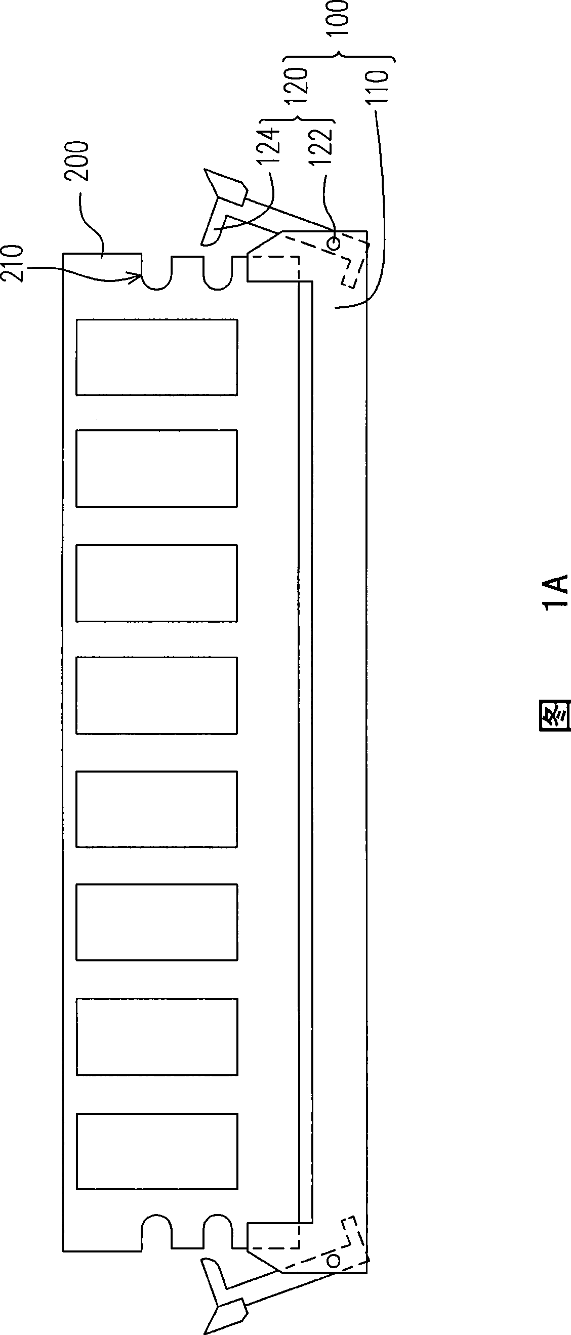
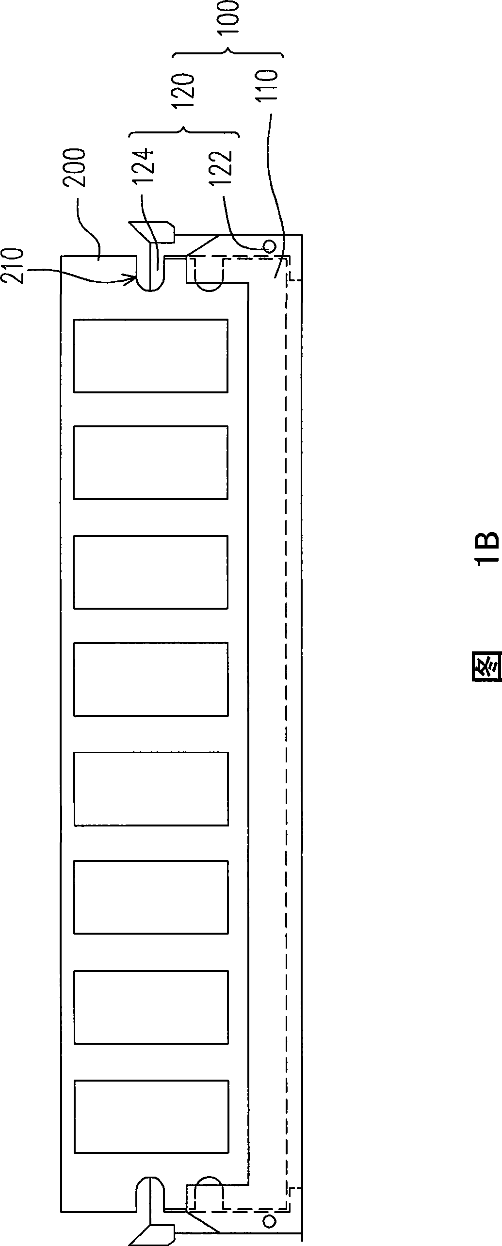
Therefore, the synchronous dynamic random access memory 200 is not only more likely to be damaged due to improper force during assembly, but also more laborious during assembly.
In addition, after the connector module 100 is vibrated, the buckle mechanism 120 is easy to loosen, so that the synchronous dynamic random access memory 200 is easy to loosen or pop out from the slot.

Method used


Image

  • Connector module
  • Connector module
  • Connector module

Examples


Embodiment Construction

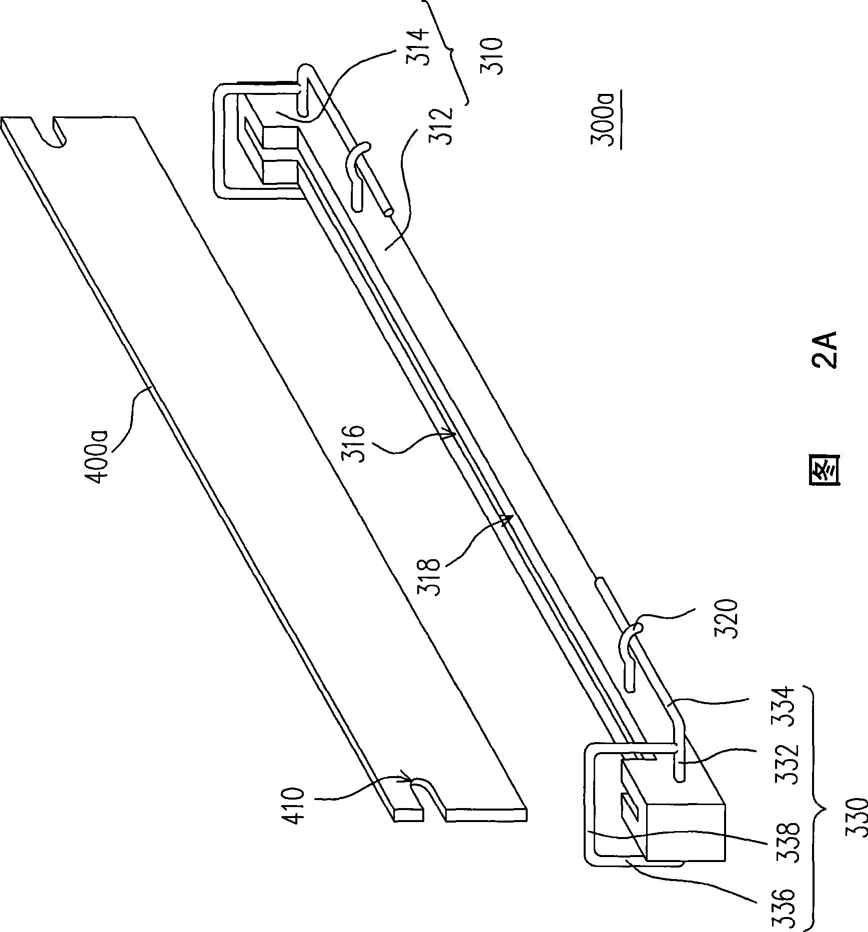
[0049] 2A and 2B are three-dimensional schematic diagrams of a connector module according to an embodiment of the present invention. 2A and 2B, the connector module 300a is suitable for assembling a memory module 400a, so that the memory module 400a can be electrically connected to a circuit board (not shown) through the connector module 300a. In this embodiment, the memory module 400a is, for example, a synchronous dynamic random access memory, and its opposite ends each have at least one recess 410 (in this embodiment, only one recess 410 is shown on each of the opposite sides of the memory module 400a depression 410).

[0050] The connector module 300 a includes a connector 310 , two limiting components 320 and two locking mechanisms 330 . The connector 310 includes a connecting portion 312 and two limiting portions 314 located at opposite ends of the connecting portion 312 , and has a slot 316 suitable for inserting the memory module 400a. The slot 316 is formed on a top...


PUM


Abstract

The invention relates to a connector module which is applicable to a memory module, wherein each of two opposite ends of the memory module is provided with at least a concave part; and the memory module comprises at least a connector, two limit pieces and two buckling mechanisms; the connector is provided with a slot suitable to be inserted in the memory module. The limit pieces are connected with the connector, and the buckling mechanisms respectively form hinge joint with two opposite ends of the connector. Each buckling mechanism is provided with a limit rod and at least a positioning rod. When the limit rods are buckled with the limit pieces, the positioning rod abuts on the concave parts to keep the memory module in the slot.

Description

technical field [0001] The present invention relates to a connector module, and in particular to a connector module suitable for synchronous dynamic random access memory (SDRAM). Background technique [0002] FIG. 1A and FIG. 1B are structural schematic diagrams of a conventional connector module inserted with a synchronous dynamic random access memory. Please refer to FIG. 1A and FIG. 1B, the connector module 100 can be used to assemble a synchronous dynamic random access memory 200, which includes a connector (connector) 110 and two buckle mechanisms pivotally connected to opposite ends of the connector 110 (latching mechanism) 120. [0003] The connector 110 has a slot (not shown), and each buckle mechanism 120 has a pivoting portion 122 and a limiting portion 124 . The buckle mechanisms 120 are pivotally connected to the connector 110 via the pivot portions 122 . In addition, opposite ends of the SDR 200 each have at least one dent 210 . [0004] When the SDRAM 200 i...

Claims


Application Information

Patent Timeline
IPC IPC(8): H01R13/62H01R13/514
Inventor 鹿影陈志丰
Owner INVENTEC CORP
Learn More