Coil ticket printing drum device

A printing cylinder and embossing cylinder technology, which is applied in printing, printing machines, rotary printing machines, etc., can solve problems affecting quality, ghosting, etc., and achieve the effect of ensuring printing quality

Active Publication Date: 2010-07-14
大连盛富商用票证印刷有限公司
View PDF1 Cites 0 Cited by
  • Summary
  • Abstract
  • Description
  • Claims
  • Application Information

AI Technical Summary

Problems solved by technology

In the printing cylinder device of this structure, the roll paper 5 moves up and down when the impression cylinder 1 moves up and down, and the impression cylinders in the multiple sets of printing cylinder devices on the printing equipment move up and down in sequence during operation, so that The roll paper fluctuates up and down, and the first few sheets will appear ghosting when printing again after skipping printing, seriously affecting the quality

Method used


Image

  • Coil ticket printing drum device
  • Coil ticket printing drum device
  • Coil ticket printing drum device

Examples


Embodiment Construction

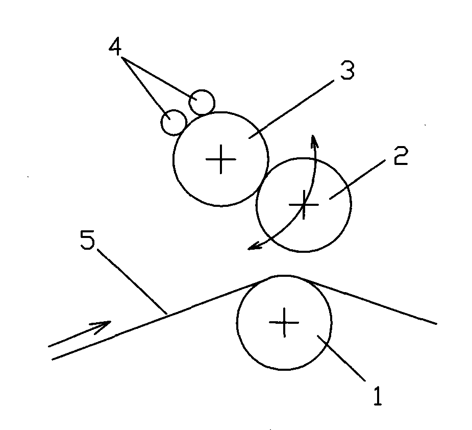
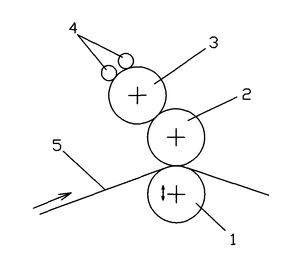
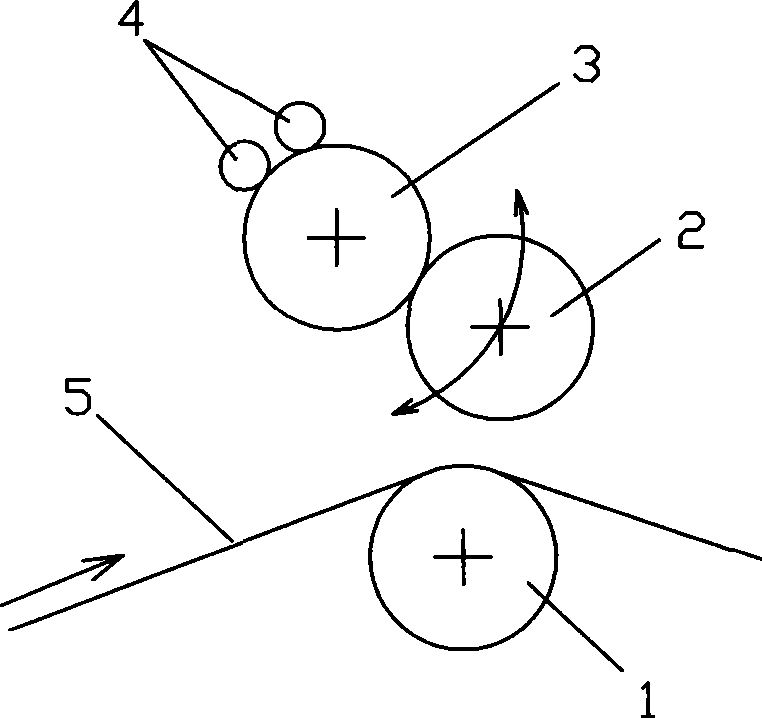
[0009] Such as figure 1 , 2 As shown: an impression cylinder 1, a rubber cylinder 2, a printing plate cylinder 3 and a forme ink roller 4 are installed on the frame. The two ends of the embossing cylinder 1 are equipped with bearings, and the bearing seat bolts matched with the bearings are fixedly installed on the frame, so that the embossing cylinder 1 can only rotate relative to the frame.

[0010] The two ends of the rubber cylinder 2 are axially connected to drive the rubber cylinder 2 to rotate along the center of the printing plate cylinder 3. The specific structure is as follows: the two ends of the rubber cylinder 2 are fitted with eccentric sleeves, and the eccentric sleeve and the frame are connected by rotation , so that the eccentric sleeve can rotate relative to the frame. The eccentric sleeve is connected with a push rod, and the push rod is connected with a piston rod matched with a cylinder installed on the frame, and the cylinder is connected with the pneu...


PUM


Abstract

The invention discloses a printing device, and more particularly relates to a printing roller device for rolling tickets, including an impression cylinder arranged on a frame, a rubber cylinder, a plate cylinder and an edition inking roller. The device is characterized in that bearings at the two ends of the impression cylinder are fixedly connected with the frame, and the two ends of the rubber cylinder are coupled with the driving system of the driving rubber cylinder, which rotates along the center of the plate cylinder. Compared with the prior art, as the impression cylinder is prevented from moving up and down during operation, the paper winding is prevented from the phenomenon of fluctuating up and down, and only the rubber cylinder is separated from the impression cylinder in jumping printing, therefore, the quality of printing is ensured and the doubled image phenomenon is avoided.

Description

technical field [0001] The invention relates to a printing device, in particular to a roll ticket printing cylinder device. Background technique [0002] Existing ticket printing cylinder device structure is: as figure 2 Shown: Impression cylinder 1, rubber cylinder 2, printing plate cylinder 3, and plate ink roller 4 connected to the power unit are installed on the frame, and the impression cylinder 1 can rotate and move up and down relative to the frame . During the working process, when the roll paper 5 passes through the device, it rides on the impression cylinder 1, the rubber cylinder 2 is tangent to the impression cylinder 1 and the printing plate cylinder 3, and the forme ink roller 4 is tangent to the printing plate cylinder 3, When a certain number of sheets are printed, the driving device moves the impression cylinder 1 down for a certain distance, so that the impression cylinder 1 and the rubber cylinder 2 are separated. At this time, no printing is performed, ...

Claims


Application Information

Patent Timeline
Patent Type & Authority Patents(China)
IPC IPC(8): B41F7/04B41F13/20B41F13/008
Inventor 赵实
Owner 大连盛富商用票证印刷有限公司
Why Eureka
Try Eureka