Base plate bonding device and method

A substrate and base technology, used in optics, instruments, electrical components, etc., can solve problems such as destroying circuits

Inactive Publication Date: 2009-04-29
SHIBAURA MECHATRONICS CORP
View PDF1 Cites 11 Cited by
  • Summary
  • Abstract
  • Description
  • Claims
  • Application Information

AI Technical Summary

Problems solved by technology

For example, when it is used to manufacture a substrate of a liquid crystal display panel, since a fine circuit is formed on the substrate, there is a risk of destroying the circuit when electrified.

Method used


Image

  • Base plate bonding device and method
  • Base plate bonding device and method
  • Base plate bonding device and method

Examples


Embodiment 1

[0027] (Example 1)( Figure 1 to Figure 10 )

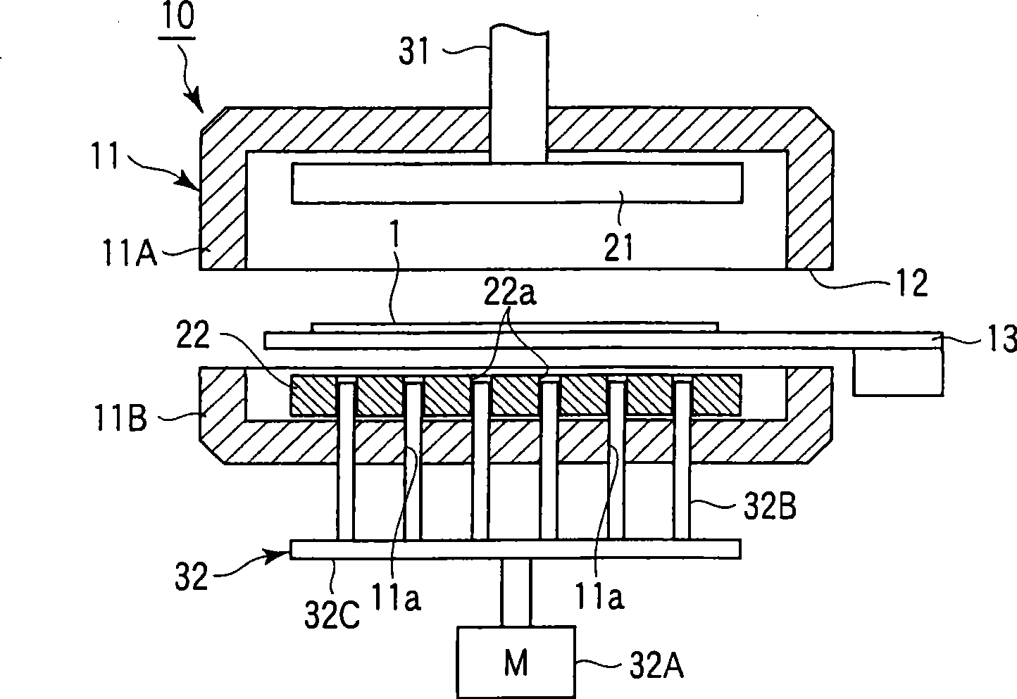
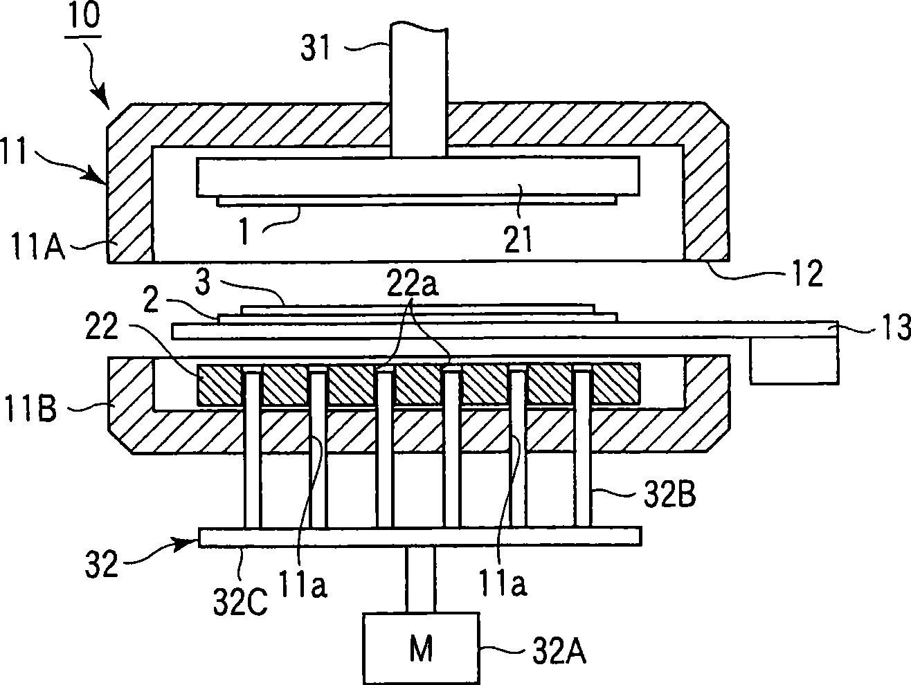
[0028] Substrate gluing device 10, such as Figure 1 to Figure 10 As shown, there is a vacuum chamber 11 (an upper chamber 11A and a lower chamber 11B) which can be opened and closed up and down, and a loading and unloading port 12 for loading and unloading the upper and lower substrates 1 and 2 is provided. The substrates 1 and 2 sucked and held by the robot arm 13 are loaded and unloaded from the loading and unloading port 12 of the vacuum chamber 11 into and out of the vacuum chamber 11 .

[0029] The vacuum chamber 11 is provided with upper and lower workbenches 21 and 22 . The upper and lower workbenches 21, 22 form a rectangular disc shape made of aluminum alloy. The upper and lower substrates 1, 2 are formed of rectangular glass substrates.

[0030] The upper workbench 21 is raised and lowered relative to the lower workbench 22 by the upper elevating device 31, and an upper substrate adsorption device (not shown) such a...

Embodiment 2

[0062] (Example 2)( Figure 11 ~ Figure 13 )

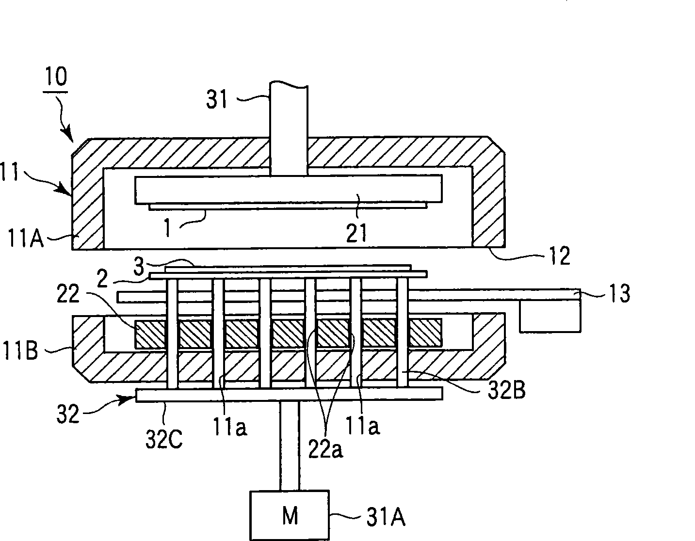
[0063] The difference between Embodiment 2 and Embodiment 1 is that after the upper substrate 1 and the lower substrate 2 are glued together, before the atmospheric pressure is restored in the vacuum chamber 11, the contact area between the upper and lower substrates 1, 2 and the upper and lower worktables 21, 22 is reduced. As an apparatus, the substrate detachment dedicated apparatus 40 was used.

[0064] The substrate detaching device 40 includes a lifting actuator 41 composed of a liquid cylinder (or a motor) and a plurality of push rods 42 arranged on the lower table 22 that are lifted and lowered by the lifting actuator 41 . The ejector rod 42 passes through the through hole 11b provided in the lower chamber 11B in a sealed manner, and further penetrates the through hole 22b formed in the lower table 22 .

[0065] In the gluing process of the upper and lower substrates 1, 2, such as Figure 11 As shown, the above-mentione...

Embodiment 3

[0071] (Example 3)( Figure 14 ~ Figure 16 )

[0072] The difference between Embodiment 3 and Embodiment 1 is that after the upper substrate 1 and the lower substrate 2 are glued together, before returning to the atmospheric pressure in the vacuum chamber 11, the contact area between the upper and lower substrates 1, 2 and the upper and lower worktables 21, 22 is reduced. As an apparatus, the substrate detachment dedicated apparatus 50 was used.


PUM


Abstract

The invention provides a substrate gluing device and method, which can prevent substrate electrification when two glued substrates are taken out from worktables so that the quality is improved. The substrate gluing device (10) has a member reducing the contact areas of upper and lower substrates (1, 2) and upper and lower worktables (21, 22) after gluing the upper substrate (1) and the lower substrate (2) and before recovering the atmospheric pressure inside a vacuum chamber (11).

Description

technical field [0001] The invention relates to a substrate bonding device and method. Background technique [0002] Conventionally, as described in Patent Document 1, the upper and lower substrates carried into the vacuum chamber are supported on the upper and lower tables, respectively, and bonded in the vacuum chamber under reduced atmospheric pressure using a substrate gluing device. After gluing the upper and lower substrates, restore the atmospheric pressure in the vacuum chamber, separate the upper workbench from the top, and simultaneously take out the two substrates from the lower workbench and move them out to the vacuum chamber. [0003] [Patent Document 1] Japanese Patent Laid-Open No. 2000-66163 [0004] In the prior art, the two substrates bonded by the substrate gluing device are taken out from the lower workbench, and the two substrates glued together are lifted from the worktable surface of the lower workbench by a lift pin built into the lower workbench, ...

Claims


Application Information

Patent Timeline
Patent Type & Authority Applications(China)
IPC IPC(8): G02F1/1333G02F1/1339
CPCH01L21/02H01L21/67092
Inventor 绢村笃司
Owner SHIBAURA MECHATRONICS CORP
Why Eureka
Try Eureka