Plastic die parting-plane air-admission stripper

A technology of plastic mold and demoulding mechanism, which is applied in the field of plastic products, can solve the problems of shortened mold life, long production cycle, and low production efficiency, and achieve the effects of small mold impact, long service life, and improved production efficiency

Inactive Publication Date: 2009-05-06
李新贵
View PDF0 Cites 13 Cited by
  • Summary
  • Abstract
  • Description
  • Claims
  • Application Information

AI Technical Summary

Problems solved by technology

The disadvantage of this method is that the production cycle is long (that is, the whole process is: injection molding machine mold opening time + push plate C part pulling or ejection time + manipulator taking product time), low production efficiency
The other is that the molded plastic product falls off automatically. When working, the push plate C must be pulled out or ejected by 3 / 4 of the product height H, otherwise the product will not fall off, resulting in two adverse consequences. One is that there is a long production cycle (i.e. The whole process is: injection molding machine mold opening time + push plate C part pull or ejection time); second, due to the weight of push plate C, it will cause friction on the guide column E of the punch and push plate C itself, and the life of the mold will be shortened

Method used


Image

  • Plastic die parting-plane air-admission stripper
  • Plastic die parting-plane air-admission stripper
  • Plastic die parting-plane air-admission stripper

Examples


Embodiment Construction

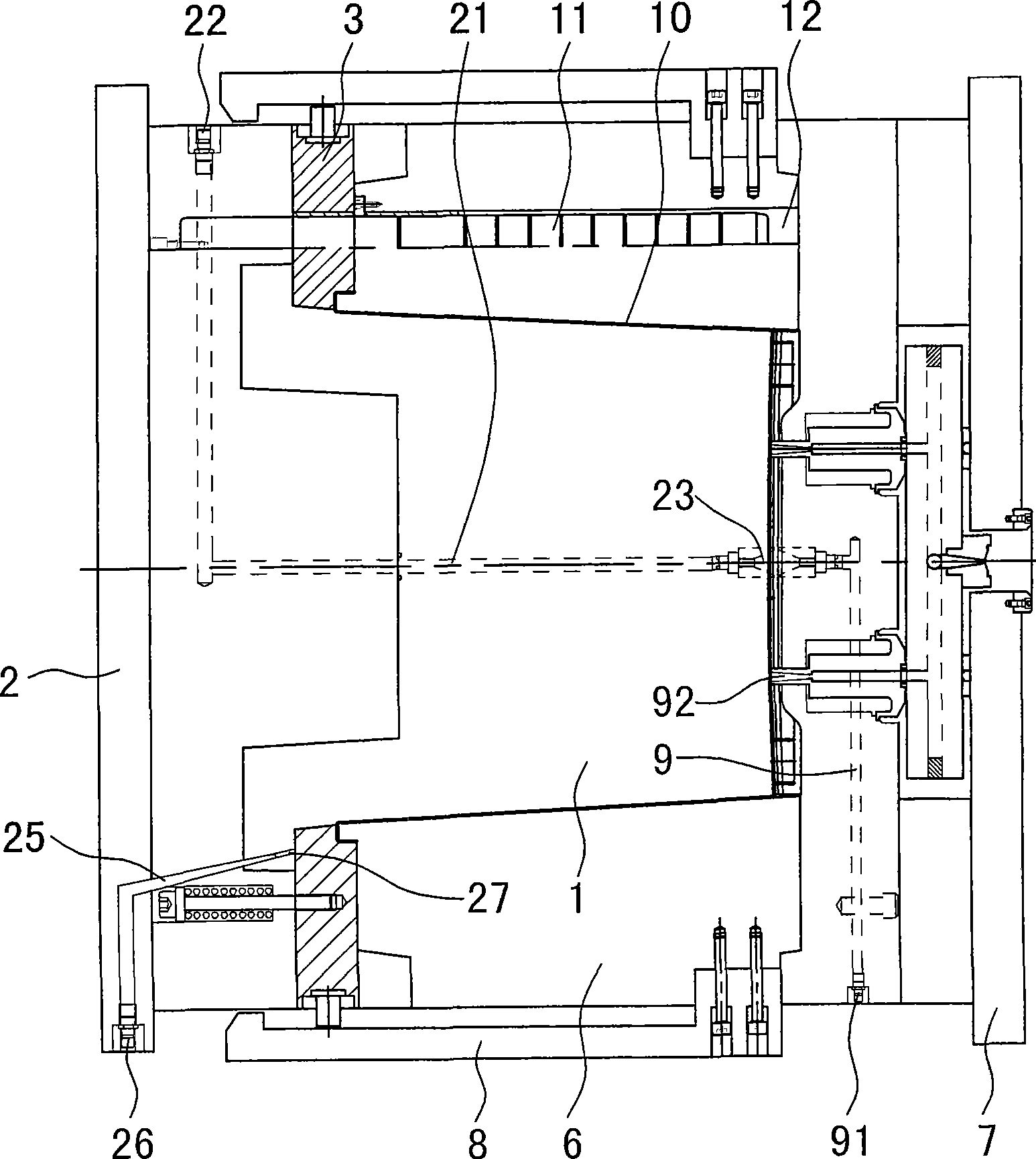
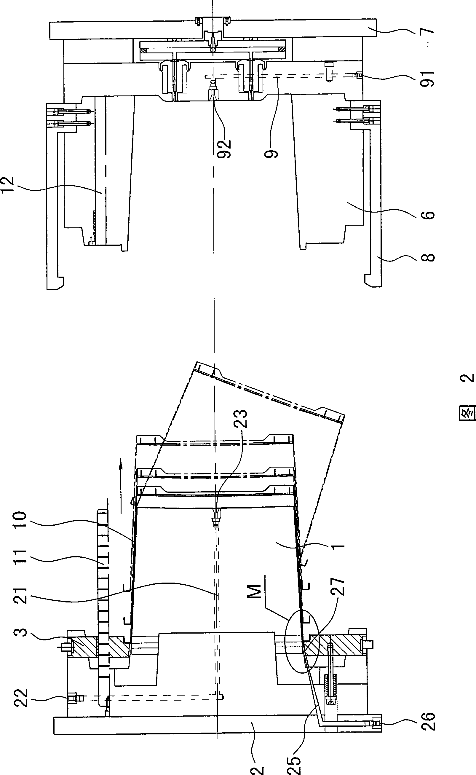
[0011] The invention discloses a plastic mold parting surface air intake and demoulding mechanism, such as figure 1 , shown in Fig. 2, comprise punch 1 and die 6 to form, push plate 3 is housed on punch, draw hook 8 is housed on die, draw hook 8 contacts with push plate 3, it is characterized in that in die 6 A blowing channel 9 is formed, and the blowing channel has an air inlet 91 and an air outlet 92, and a top air channel 21 and a plurality of parting surface air inlet channels 25 are formed in the punch 1, and the top air channel 21 has an air inlet 22 And exhaust port 23, each parting surface air inlet channel 25 has injection port 26 and blowing port 27 respectively, and the air-flow that blowing port 27 produces is positioned at the space between punch 1 and plastic product 10 respectively. The demoulding process is as follows: Before the mold is divided, the air inlet 91 of the air blowing channel 9 is first aired. The air inlet 22 of 21 takes in air, and 2 to 3 seco...


PUM


Abstract

A plastic mold split surface gas inlet demoulding mechanism consists of a convex mold and a concave mold, wherein, a pulling slab is arranged on the convex mold, a pulling hook is arranged on the concave mold, and the pulling hook is contacted with the pulling slab.The mechanism is characterized in that the concave mould is provided with a blowing passage which is provided with a gas inlet and a gas outlet, the convex mold is provided with a top wind passage and a plurality of split surface gas inlet passages, the top wind passage is provided with a wind inlet and a wind outlet, the gas inlet passages of the spit surfaces are respectively provided with a wind injecting port and a wind blowing port, the gas flow produced from the wind blowing ports is positioned in the gap between the convex mold and the plastic production. The demoulding time of the demoulding mechanism is short, the plastic production can automatically fall off within the molding completion time of the injection molding machine, and therefore, the production efficiency is improved. On the other hand, the pulling path of the pulling slab is short, the influence to the mold is small, and the service life is long.

Description

technical field [0001] The invention relates to a demoulding mechanism of a plastic mold, and is mainly suitable for plastic products with closed tops and surroundings, such as plastic boxes, barrels and other products. Background technique [0002] Plastic products need to be released from the mold after injection molding. The existing demoulding mechanism can be divided into two types: one is about 1 to 2 seconds before the mold (its structure is shown in Figure 3) is divided, the first is the concave The air inlet of part A of the mold is used to keep the outer wall of the product and the inner wall of the concave mold in a vacuum state, and the product will move together with the punch. Push plate C (in addition to the way of pulling out with a pull rod, the way of jacking out by an oil cylinder can also be used), so that the product D is separated from the punch, and then taken out with a manipulator. The disadvantage of this method is that the production cycle is long...

Claims


Application Information

Patent Timeline
Patent Type & Authority Applications(China)
IPC IPC(8): B29C33/46B29C45/43
Inventor 李新贵
Owner 李新贵
Why Eureka
Try Eureka