Fan

A technology of fans and nozzles, applied in the field of indoor fans, can solve problems such as large working area and occupation of users, and achieve the effect of reducing moving parts, reducing speed and maintaining overall output.

Inactive Publication Date: 2009-05-06
DYSON TECH LTD
View PDF9 Cites 127 Cited by
  • Summary
  • Abstract
  • Description
  • Claims
  • Application Information

AI Technical Summary

Problems solved by technology

[0007] It is not always possible to position the fan as described above close to the user, as the bulky shape and construction means that the fan takes up a lot of the user's work area

Method used


Image

  • Fan
  • Fan
  • Fan

Examples


Embodiment Construction

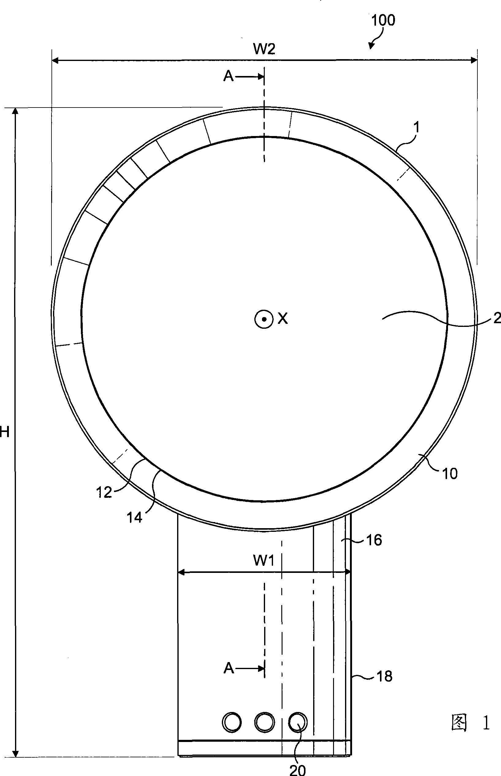
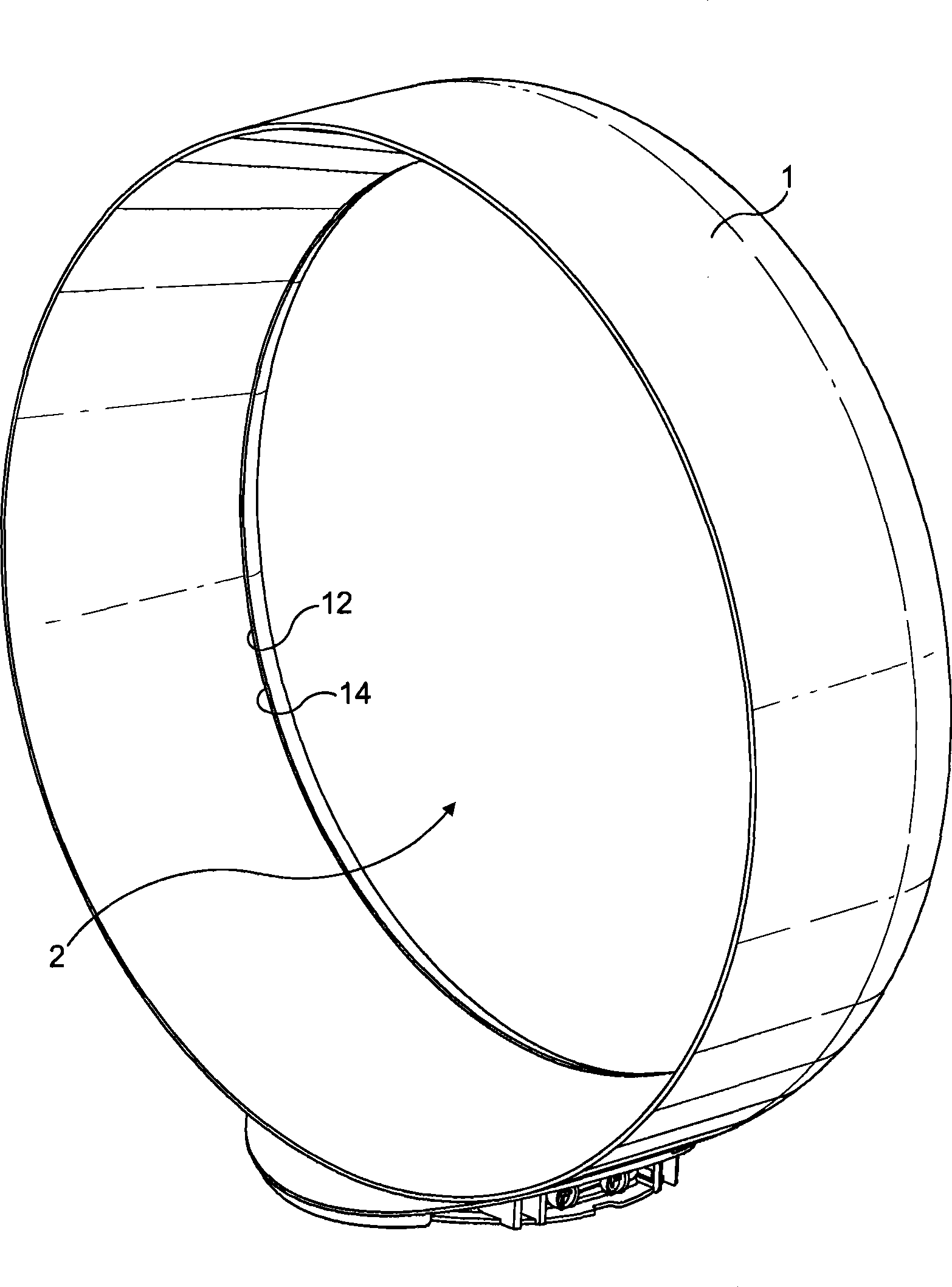
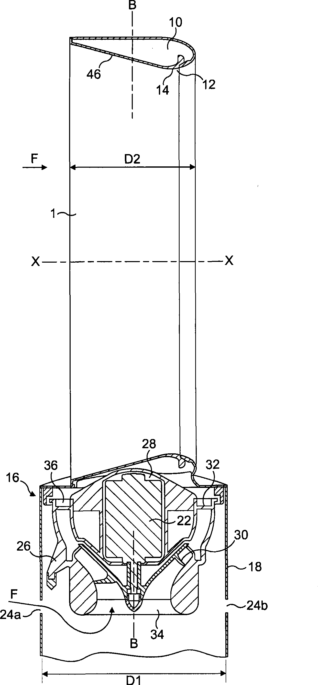
[0035] FIG. 1 shows an example of the fan device 100 viewed from the front of the apparatus. The fan device 100 includes an annular nozzle 1 which defines a central opening 2. Refer again figure 2 with image 3 , The nozzle 1 includes an internal channel 10, an exhaust port 12 and a Coanda surface 14 close to the exhaust port 12. The Coanda surface 14 is arranged such that the main airflow that exits from the exhaust port 12 and is guided to flow through the Coanda surface 14 is amplified by the Coanda effect. The nozzle 1 is connected to and supported by a base 16 having an outer cover 18. The base 16 includes a plurality of selection buttons 20 accessible through the outer cover 18, and the fan device 100 can be operated through the selection buttons. In Figure 1 and image 3 The fan unit shown in has a height H, a width W, and a depth D. The nozzle 1 is arranged to extend substantially orthogonally with respect to the axis. The height H of the fan device is perpendicular to th...


PUM


Abstract

The present invention discloses a fan assembly for generating air flow. The bladeless fan assembly comprises a nozzle mounted on a base, and the base is used to receive components for generating air flow through the nozzle. The nozzle comprises an interior passage for receiving the air flow from the base and an air outlet through which the air flow is ejected. The nozzle limits a mouth extending basically orthogonally in relation to a shaft, the air outside the fan assembly is pumped by the air flow ejected from the air outlet through the mouth, the nozzle and the base have a depth in the shaft direction, and the depth of the base is no more than two times of the nozzle depth. The fan is provided with means for generating air flow and cooled air flow without a blade fan, namely a bladeless fan generates air flow. Selectively, the fan assembly has a height extending from the base tag end far from the nozzle to the nozzle tag end far from the base, and a width being vertical to the height, the height and the width are all vertical to the shaft, and the base width is no more than 75% of the nozzle width. The configuration ensures the fan assembly to have a compact structure.

Description

Technical field [0001] The invention relates to a fan device. In particular, but not exclusively, the present invention relates to an indoor fan, such as a desktop fan, for generating air circulation and air flow in a room, office or other indoor environment. Background technique [0002] Many types of indoor fans are known to us. Generally, a conventional fan includes a single set of blades or wings installed to rotate around an axis, and a driving device installed around the axis to rotate the entire set of blades. Indoor fans of various sizes and diameters are available. For example, ceiling fans can be at least 1 m in diameter, and are usually installed in a manner of being suspended from the ceiling and positioned to provide downward airflow and cool the room. [0003] On the other hand, the diameter of a desktop fan is generally about 30 cm, and it is usually free to place and portable. In a standard desktop fan configuration, a single set of blades is placed close to the u...

Claims


Application Information

Patent Timeline
Patent Type & Authority Applications(China)
IPC IPC(8): F04F5/14F04F5/46F04F5/44
CPCF04F5/46F04D25/08F04F5/16
Inventor 彼得·D·甘马克弗雷德里克·尼古拉斯凯文·J·西蒙斯
Owner DYSON TECH LTD
Why Eureka
Try Eureka