Mager vorgemischte dual-fuel-ringrohrbrennkammer mit radial-mehrring-stufenduse

A burner, dual-fuel technology, used in combustion chambers, combustion methods, combustion equipment, etc., can solve problems such as expensive and uncertain, and units that cannot be used

Inactive Publication Date: 2009-05-06
GENERAL ELECTRIC CO
View PDF0 Cites 39 Cited by
  • Summary
  • Abstract
  • Description
  • Claims
  • Application Information

AI Technical Summary

Problems solved by technology

Thus, if too much skew is required to smooth out dynamics or instabilities, a violating NO X emission limit conditions that may render the unit unusable
LP combustion dynamics in industrial gas turbines are typically passively reduced by methods which are often a process of trial and error which can be costly and uncertain

Method used


Image

  • Mager vorgemischte dual-fuel-ringrohrbrennkammer mit radial-mehrring-stufenduse
  • Mager vorgemischte dual-fuel-ringrohrbrennkammer mit radial-mehrring-stufenduse
  • Mager vorgemischte dual-fuel-ringrohrbrennkammer mit radial-mehrring-stufenduse

Examples


Embodiment Construction

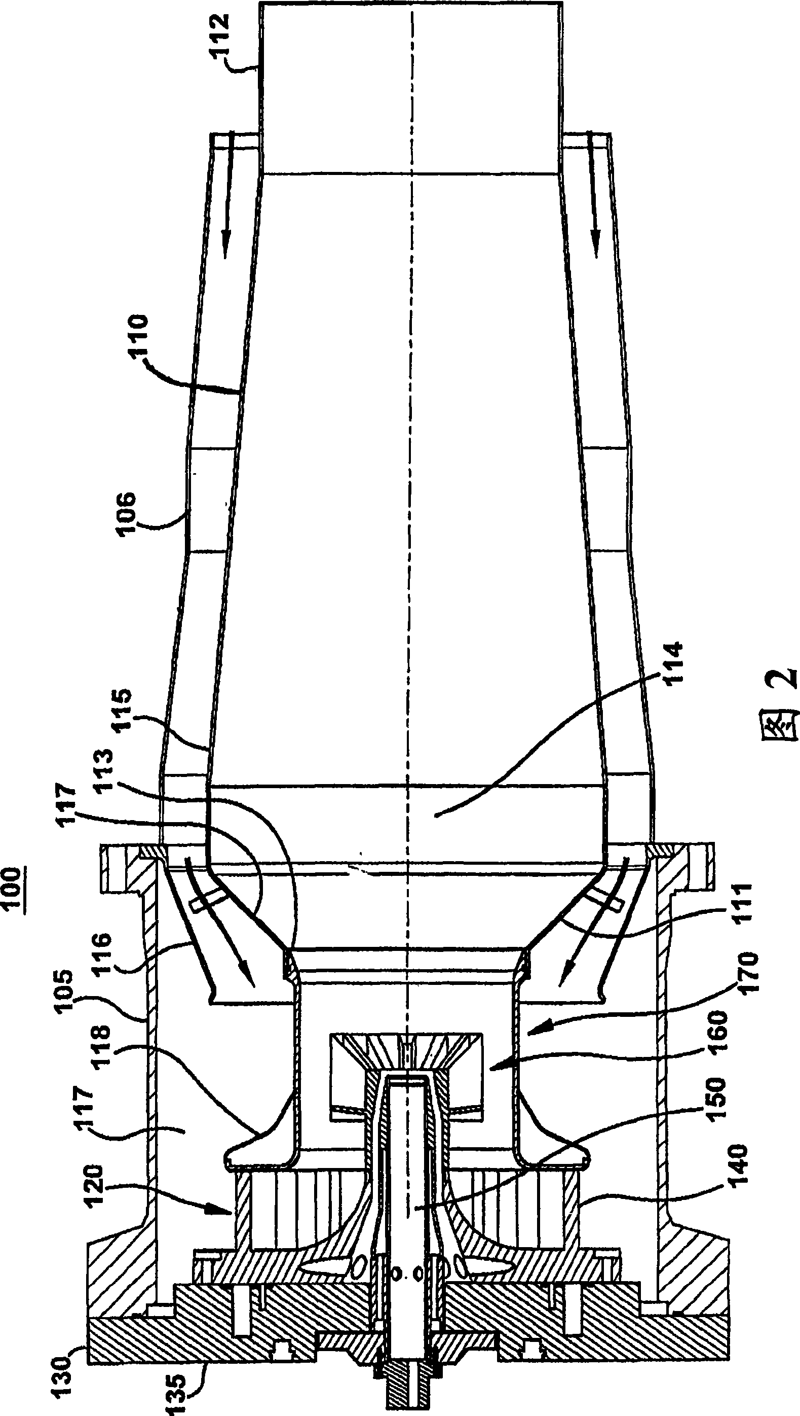
[0152] The following embodiments of the present invention have many advantages, including several innovative and unique features as follows: (1) Allows for the replacement of multiple (e.g., six) premixing nozzles (each can) and combustor cover, thereby achieving a significant reduction in parts count, saving cost, and significantly simplifying the head end of the combustor; (2) using a dome diffuser design to convectively cool the dome of the liner from the back, and in Allows fuel and air to be premixed in large radial nozzles while simultaneously restoring static pressure, resulting in less parasitic pressure loss and making more air available for premixing; (3) provides a relatively low pressure drop (e.g. <4%) the ability to quickly (e.g. <3msec) and completely vaporize and mix large quantities of fuel (~2lbm / sec) and air (~60lbm / sec); and (4) using gaseous or liquid fuels, It does this by strategically distributing or distributing heat release (in time and space) and fue...


PUM


Abstract

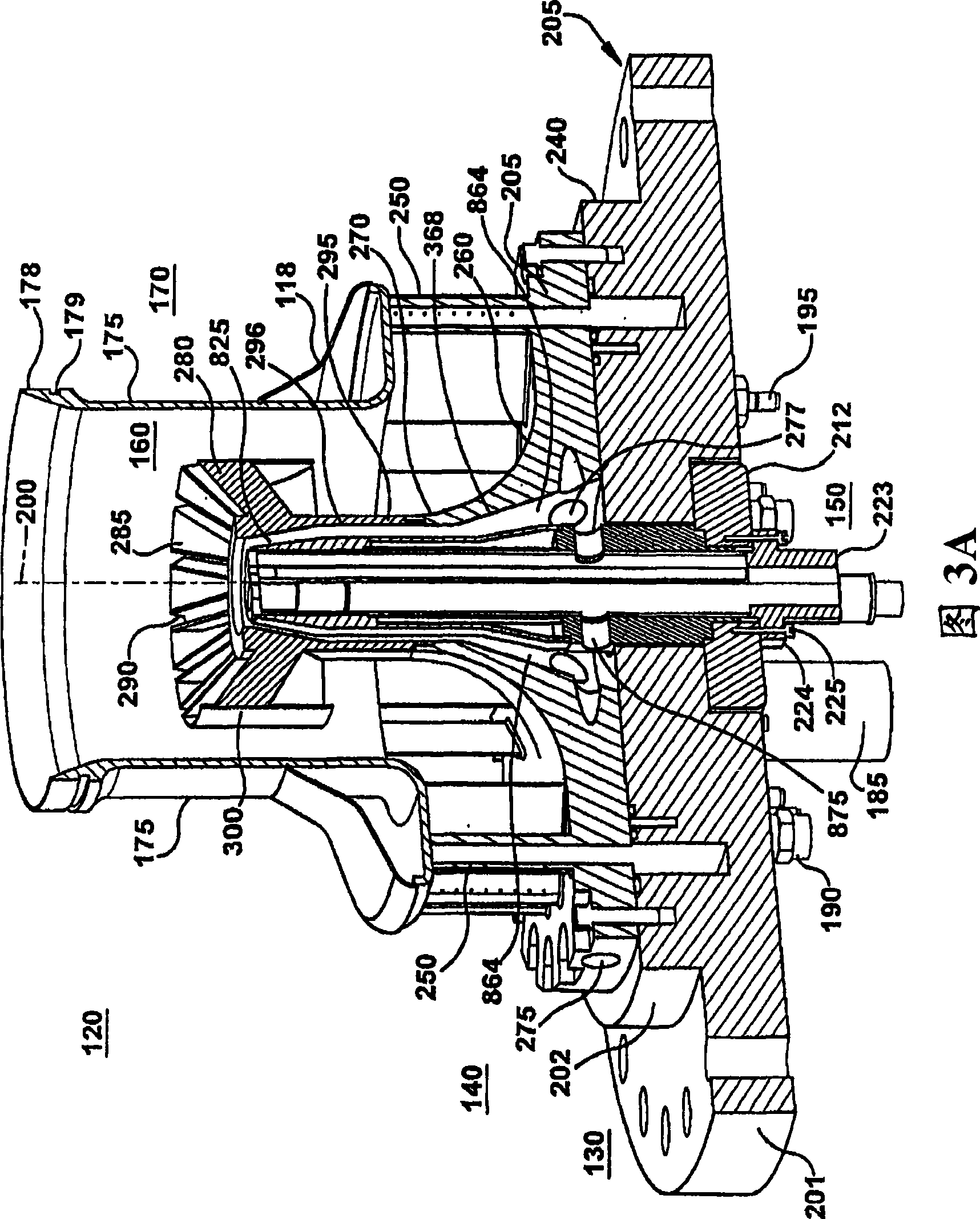
A lean premixed, radial inflow, multi-annular staged nozzle for creating three independent combustion zones within a can-annular, dual-fuel gas turbine combustor is provided. The nozzle includes a pilot zone fueled by a gas pilot nozzle and center cartridge; a flame holder zone fueled by an inner main gas fuel; a main flame zone fueled by an outer main gas fuel; a main radial swirler for mixing a portion of incoming air to the nozzle with the inner main gas fuel supply and the outer main gas fuel supply; an endcover; and means for controlling the ratio of an inner main gas fuel supplied and an outer main gas fuel supplied.

Description

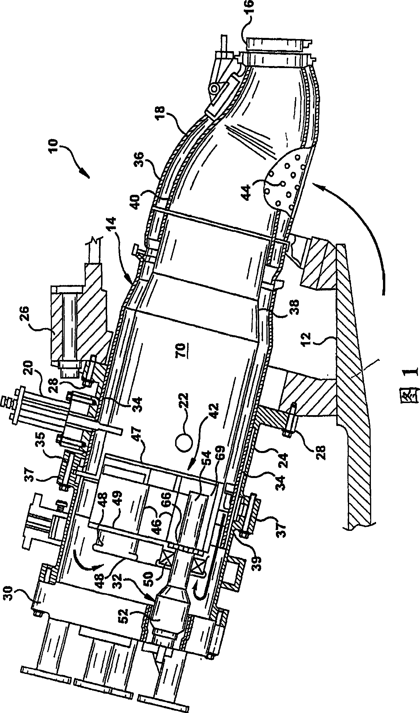
technical field [0001] This invention relates generally to gas turbine combustors and, more particularly, to a lean premix, centripetal, multi-annular, staged nozzle for a can-shaped annular dual-fuel combustor that significantly reduces Or eliminate combustion dynamics (combustion dynamics). Background technique [0002] Figure 1 shows a prior art combustor for a heavy industrial gas turbine 10 comprising a compressor 12 (partially shown), a plurality of combustors 14 (one combustor shown for convenience and clarity) and a turbine 16 (represented by a single lobe). Although not specifically shown, turbine 16 is drivingly coupled to compressor 12 along a common axis. Compressor 12 pressurizes intake air which then flows countercurrently to combustor 14 where it is used to cool combustor 14 and provide air for the combustion process. Although only one combustor 14 is shown, the gas turbine 10 includes a plurality of combustors 14 positioned around its periphery. Transitio...

Claims


Application Information

Patent Timeline
Patent Type & Authority Applications(China)
IPC IPC(8): F23R3/58F23R3/38
CPCF23R3/14Y02T50/675F23R3/36F23R3/286F23R3/343Y02T50/60
Inventor G·A·博德曼T·E·约翰逊J·F·麦康瑙海A·桑亚尔
Owner GENERAL ELECTRIC CO
Why Eureka
Try Eureka