
Winding device of armature and method

A technology of a winding device and a winding method, applied in the directions of electromechanical devices, electrical components, electric components, etc., can solve the problem of difficulty in improving the full rate of the slot, etc.

Active Publication Date: 2009-05-06
MITSUBA CORP
View PDF1 Cites 7 Cited by
  • Summary
  • Abstract
  • Description
  • Claims
  • Application Information

AI Technical Summary

Problems solved by technology

[0005] However, as described in the above-mentioned Patent Document 1, if only a guide member for guiding the metal wire toward a pair of grooves is simply used, since the guide position from the guide member into the groove is already determined, it is difficult to improve the groove fill rate. a question

Method used


Image

  • Winding device of armature and method
  • Winding device of armature and method
  • Winding device of armature and method

Examples


Embodiment Construction

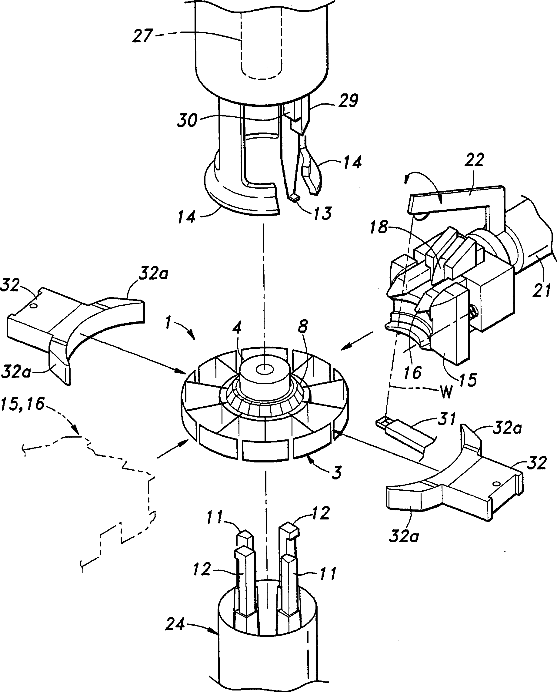
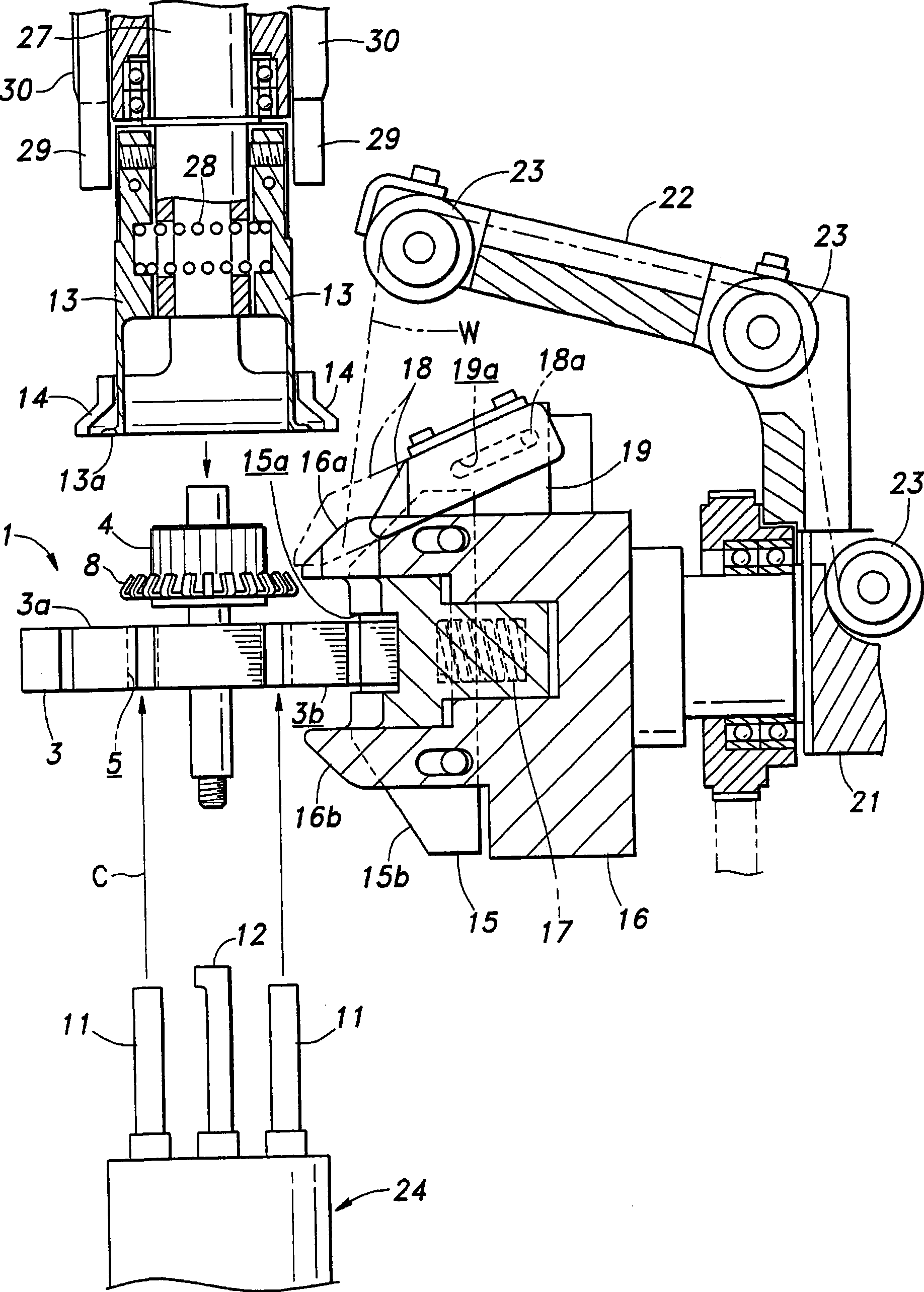
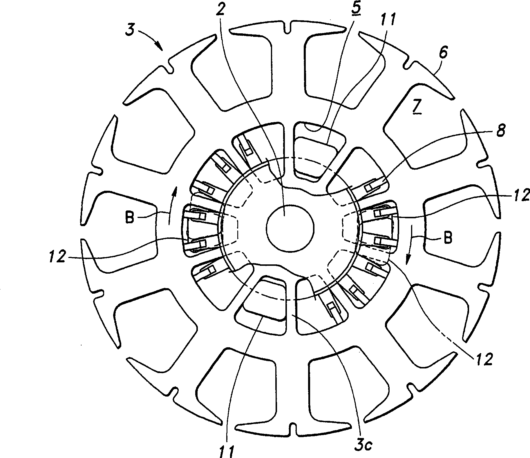
[0028] Hereinafter, embodiments of the present invention will be described with reference to the drawings. figure 1 It is a figure which schematically and schematically shows the whole of the winding device to which this invention was applied. The armature 1 to be wound by this device is a flat type as shown in the figure, and is used in a flat motor whose axial direction is shorter than the outer diameter.

[0029] such as with figure 2 with image 3 As shown together, the armature 1 has a thin, large-diameter iron core 3 and a small-diameter commutator 4 , which are arranged coaxially and fixed on the shaft 2 . The iron core 3 of the illustrated example is an iron core formed by laminating steel sheets. The iron core 3 has an annular wall on a circumference passing through a substantially midpoint in the radial direction. A plurality of axial through holes 5 penetrating the axial direction of the iron core 3 are provided at equal intervals in the direction, and a predete...


PUM


Abstract

The invention provides a winding device and method of an armature to improve slot fullness rate aiming at a pancake motor. The winding device is provided with: a variable guiding part having an arc groove having an arc abutting surface abutted with the outer peripheral face of an iron core; and a guide portion that guides the wire from the outer peripheral surface of the core to a pair of slots; and a movable guiding part that supports the variable guiding part so as to be freely moved in the radial direction of the iron core. Moreover, a spring force is applied on the movable guiding part bya compressed spiral spring; the movable guiding part is provided with the guide portion; the end face of the guide portion along the axial direction of the iron core is extended out more inwardly to the iron core than the variable guiding part. As the position of the variable guiding part guiding metal wires into the slot can be freely set in the radial direction of the iron core, the position ofthe initial winding relative to the slot is as inward the semi-diameter direction of the iron core as possible in the condition of double-layer winding, thereby being capable of improving slot fullness rate.

Description

technical field [0001] The present invention relates to a winding device and method for an armature for winding metal wire around a core having a plurality of slots. Background technique [0002] Hitherto, as a winding device for winding a metal wire around an iron core having a plurality of slots, there have been various devices, among which there is a device provided with a flyer and a guide member, the The flyer rotates around an axis perpendicular to the iron core; the guide member is used to guide the metal wire conveyed from the flyer toward a predetermined pair of grooves, by feeding the wire from the flyer and rotating the flyer at the same time, relative to The plurality of slots winds a metal wire in a predetermined number of turns into a predetermined pair of slots (for example, refer to Patent Document 1). [0003] Patent Document 1: Japanese Patent Laid-Open No. 2004-274850 [0004] On the other hand, in the iron core of a flat motor, the wires are wound in sl...

Claims


Application Information

Patent Timeline
Patent Type & Authority Applications(China)
IPC IPC(8): H02K15/09H02K15/04
Inventor 横山佳之星野明夫奈良徹也新井和夫后闲一仁
Owner MITSUBA CORP
Learn More