Supercharge Your Innovation With Domain-Expert AI Agents!

Implant optimization scheme

A technology for implanting ions and substrates, which is applied to semiconductor devices, electrical components, circuits, etc., and can solve problems such as the operation of transistor devices

Inactive Publication Date: 2009-05-06
TEXAS INSTR INC
View PDF0 Cites 8 Cited by
  • Summary
  • Abstract
  • Description
  • Claims
  • Application Information

AI Technical Summary

Problems solved by technology

Although the distance (d) can be estimated using the equation d=htan(θ), it still produces an undoped / underdoped region 170 defined by the distance (d), which is often prone to severe degradation of the transistor device 140 operational problems

Method used


Image

  • Implant optimization scheme
  • Implant optimization scheme
  • Implant optimization scheme

Examples


Embodiment Construction

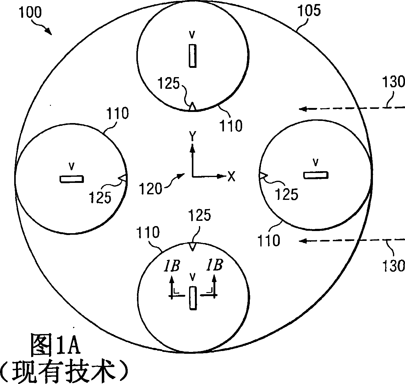
[0015] [0015] For purposes of completeness, a few terms need to be clarified before going into the details of the present invention. For example, the term "chord" or "chordwise" as used herein is intended to mean a line connecting any two points at or on the perimeter of the implantation disk other than a line intersecting the center point of the ion implantation disk. Where the injection disk is circular, the term "chord" or "chordwise" means any straight line connecting any two points on the circumference of a circular injection disk that does not intersect the center point of the circular injection disk, and is The straight lines where the center points of the injection disk intersect define the diameter of the circular injection disk. On the other hand, when the injection disk is polygonal, the term "chord" or "chordwise" means any straight line connecting any two points on the perimeter of the polygonal injection disk that does not intersect the center point of the polygo...


PUM


Abstract

The present invention provides a method for implanting ions in a substrate and a method for manufacturing an integrated circuit. The method for implanting ions in a substrate, among other steps, including placing a substrate ( 410 ) on an implant platen ( 405 ) such that a predominant axes ( 430 ) of the substrate ( 410 ) is rotated about 30 degrees to about 60 degrees or about 120 degrees to about 150 degrees offset from a radial with respect to the implant platen ( 405 ), and further wherein the substrate ( 410 ) is not tilted. The method further includes implanting ions into the substrate ( 410 ), the rotated position of the predominant axes ( 430 ) reducing shadowing.

Description

technical field [0001] [0001] The present invention relates generally to implantation optimization schemes, and more particularly to implantation optimization schemes in which the major axis of the substrate into which ions can be implanted is chord-wise to the implantation disk. Background technique [0002] [0002] Advanced integrated circuit design requires precise control of beam incidence angles. While there are many different types of beam incidence angle errors, three of the more common types are: cone angle errors, beam deflection errors, and parallelism errors across the entire wafer surface. Cone angle errors are typically the result of cone angle effects caused by the geometry of the wafer scanning system. Taper angle errors cause variations within the wafer. For example, the beam angle error can be approximately -x degrees on one side of the wafer, approximately zero degrees at the center of the wafer, and approximately +x degrees on the opposite side of the waf...

Claims


Application Information

Patent Timeline
IPC IPC(8): H01L21/336H01L21/76H01L21/425H01L21/265H01L21/8238
CPCH01L21/26586H01L21/823814H01L29/66659H01L21/265
Inventor J·D·伯恩斯坦L·S·罗伯逊S·N·吉内姆N·马哈林盖姆B·G·莫泽
Owner TEXAS INSTR INC
Features
  • R&D
  • Intellectual Property
  • Life Sciences
  • Materials
  • Tech Scout
  • Unparalleled Data Quality
  • Higher Quality Content
  • 60% Fewer Hallucinations
Learn More