Ultra-wide angle objective lens

An imaging objective lens, ultra-wide-angle technology, applied in optical components, instruments, optics, etc., can solve problems such as distortion of the image surface

Inactive Publication Date: 2009-05-13
阿里克斯·宁
View PDF4 Cites 2 Cited by
  • Summary
  • Abstract
  • Description
  • Claims
  • Application Information

AI Technical Summary

Problems solved by technology

It should be noted that the image plane produced b

Method used


Image

  • Ultra-wide angle objective lens
  • Ultra-wide angle objective lens
  • Ultra-wide angle objective lens

Examples


Embodiment Construction

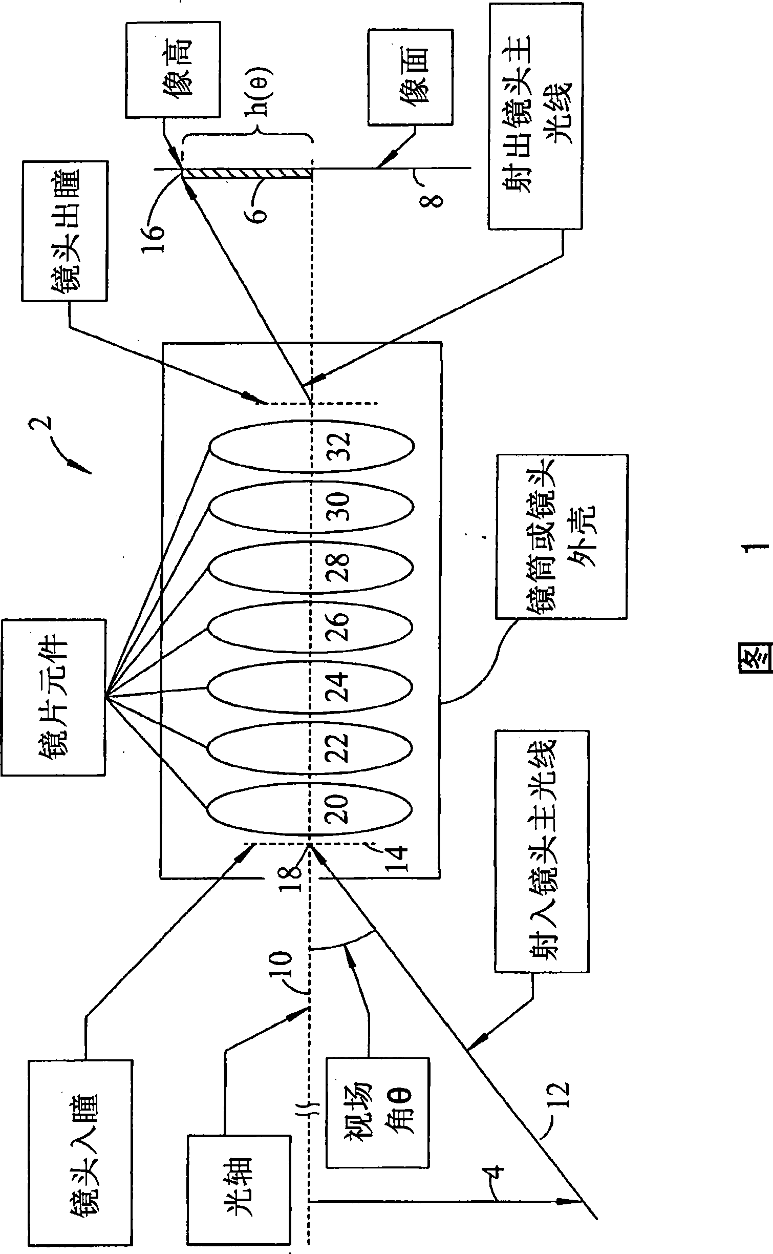
[0036] Fig. 1 is a brief schematic diagram of the ultra-wide-angle lens 2, as shown in the figure, the object 4 refers to a downward arrow, and it is located in the object space on the left side of Fig. 4, and form an image 6 on the image plane 8 with the light from the object 4. Image 6 is the image of object 4.

[0037] The legend "Lens Entrance Pupil" is one of several legends, each defining an additional feature on the optical schematic. The "optical axis" diagram is shown as optical axis 10. The legend of field angle θ" refers to the angle between the chief ray 12 and the optical axis 10, and the chief ray 12 enters the entrance pupil 14 of the lens. The legend "image height" is located at the apex of the image 16. The height h(θ) of the image is the angle between the optical axis and the Like 16 for the distance between vertices.

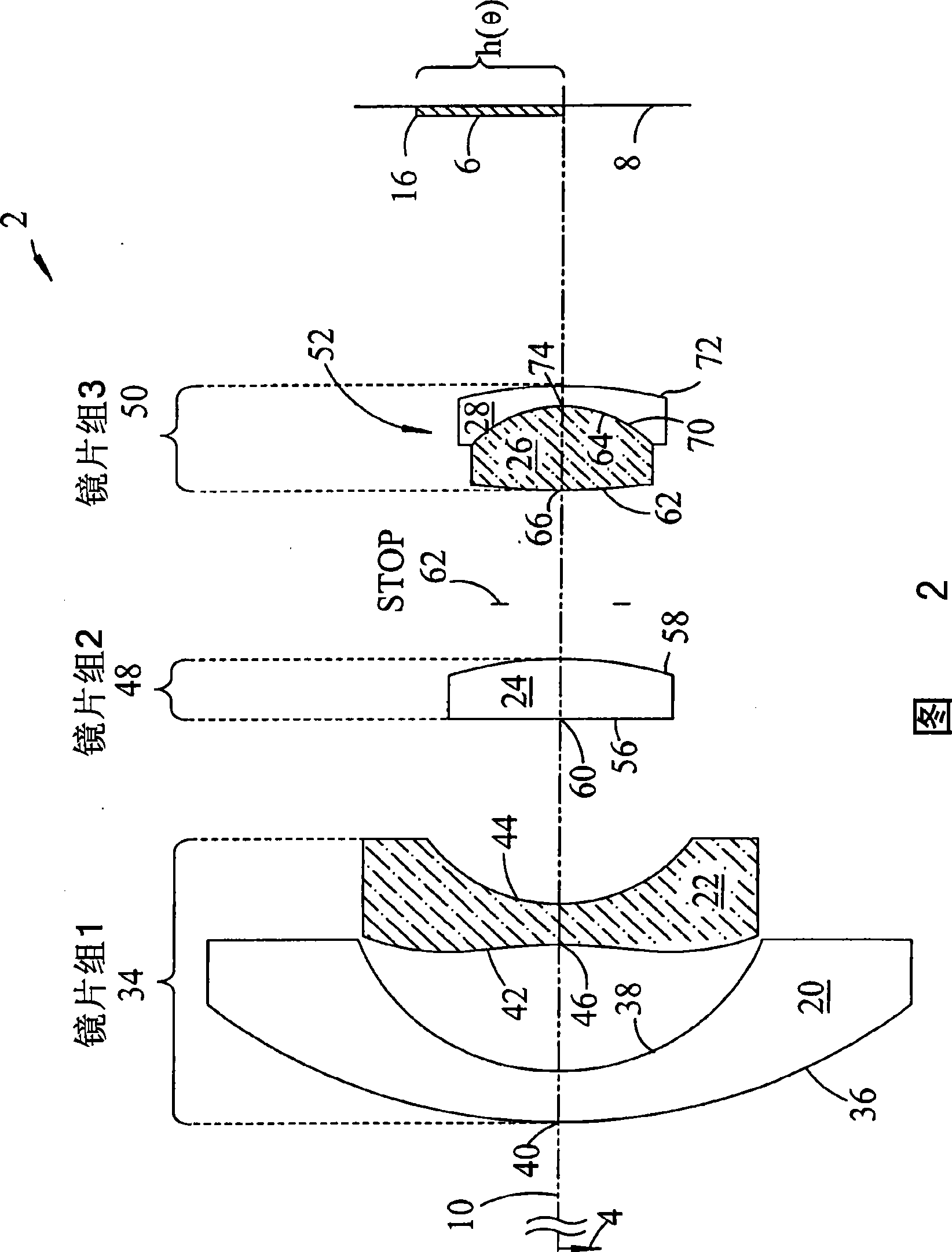
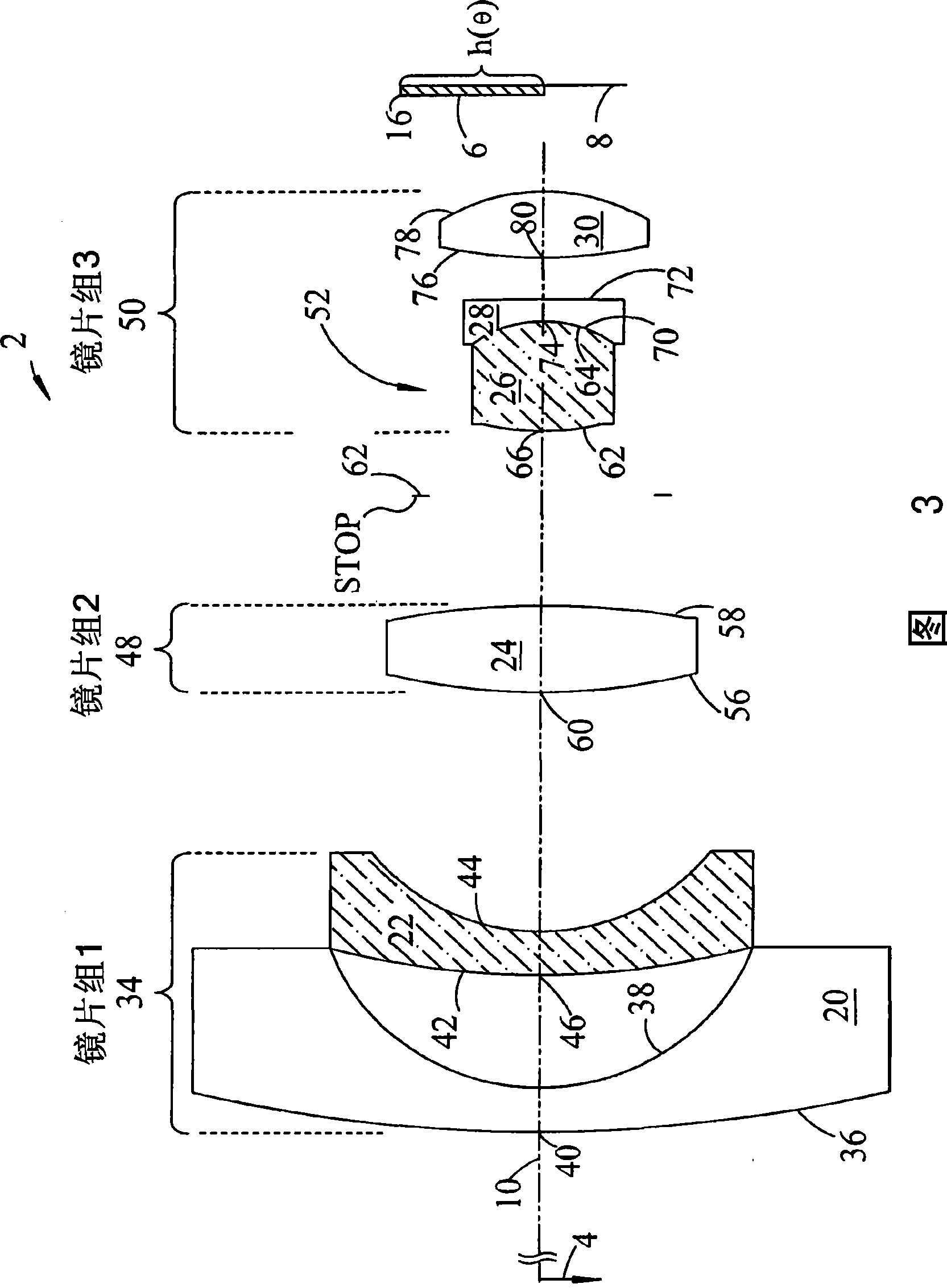
[0038] The chief ray 12 extends to the center of the entrance pupil 18 of the lens, then passes through seven optics 20 , 22 , 24 , 26 , 2...


PUM


Abstract

A ultra-wide angle objective lens comprising a first group having a first lens element having a convex object surface facing the object and a concave image surface facing the image plane, and a second aspheric lens element, the second aspheric lens element having a varying power that is negative at its vertex; and that increases positively with radial distance from the vertex. A second group has at least one lens element and a positive power. A third group has at least a first and a second lens element and a positive power. The ratio of the total track to the focal length satisfies the condition that TT/fo = < 33 and the image height on a focal plane is h(theta) > f*theta, where h(theta) is the image height formed by an off-axis chief ray having a field angle theta, and f is the effective focal length of the lens.

Description

[0001] This application claims priority from US Provisional Patent 60 / 791,032 filed 04 / 10 / 06 by the same inventor for an ultra wide angle imaging objective. [0002] STATEMENT REGARDING FEDERALLY SPONSORED RESEARCH OR DEVELOPMENT [0003] 1 does not exist [0004] The name of any organization with a co-development agreement. [0005] 2 does not exist. [0006] There are reference materials for missions submitted in CD-ROM form. [0007] 3 does not exist [0008] Microfilm Annex Reference. [0009] 4 does not exist [0010] See required list. [0011] does not exist. [0012] technical field of invention [0013] The present invention is a compact lens used in digital cameras, and is especially suitable for super large field of view lenses or fisheye lenses, which are used in very compact digital cameras. Examples of such lenses are also used in surveillance cameras or some other very small electronic devices. technical background [0014] Imaging lenses with a large ...

Claims


Application Information

Patent Timeline
IPC IPC(8): G02B13/06G02B13/04G02B13/18
Inventor 阿里克斯·宁
Owner 阿里克斯·宁
Why Eureka
Try Eureka