Dual-lensed unitary optical receiver assembly

a unitary optical receiver and unitary optical technology, applied in the field of duallensed unitary optical receiver assembly, can solve the problems of reducing the size of the receiver, increasing the difficulty of performing active alignment, and reducing the cost and complexity of the process, so as to eliminate the need for flex circuit

Inactive Publication Date: 2009-07-07
CISCO TECH INC
View PDF24 Cites 36 Cited by
  • Summary
  • Abstract
  • Description
  • Claims
  • Application Information

AI Technical Summary

Benefits of technology

[0008]In accordance with the present invention, a unitary receiver assembly is formed to include a V-groove aligned with a collimating lens (the lens formed along a surface perpendicular to the V-groove). An optical fiber is disposed along the V-groove and is used to bring the received optical signal into the unitary assembly. Upon passing through the collimating lens, the received optical signal will intercept a turning mirror wall that directs the signal downward, through a focusing lens (also molded in the unitary assembly), and then into a photosensitive device. Advantageously, the photosensitive device is disposed in passive alignment with the focusing lens, allowing for a received signal to be coupled from an incoming optical fiber to a photosensitive device without needing any type of active alignment therebetween. The utilization of a focusing lens allows for a received signal to be efficiently coupled into the photosensitive device. Therefore, a small active area photodiode (as used in high speed applications) is suitable for use in the unitary module of the present invention. Moreover, by directly molding the collimating and focusing lenses (and V-groove) into the unitary receiver module, passive alignment between the fiber and photosensitive device is achieved, reducing the cost and complexity of the receiver arrangement.
[0010]It is a feature of the present invention that the use of molded lenses within the unitary assembly, in combination with the V-groove and turning mirror, allows for an array structure to be easily formed, accommodating a plurality of these features, disposed along the surface of a single assembly. Such an array of molded lenses may alternatively be used in association with an inserted prism element and single input fiber carrying multiple wavelength signals to form a demultiplexing device.
[0011]In prior art optical receiver / transceiver assemblies, the optical port axis is typically parallel to the supporting substrate surface. The assembly generally comprises two components: a TO can optical port assembly (containing a photodiode and a transimpedance amplifier), and a flex circuit for connecting the TO can to the substrate. The arrangement of the present invention eliminates the need for the two separate elements and particularly eliminates the need for the flex circuit inasmuch as the photodiode is directly located on the substrate as part of the unitary assembly.

Problems solved by technology

The number and placement of these elements of an optical receiver has heretofore limited the ability to reduce the size of the receiver, as well as its cost and complexity.
This small active area makes the process of performing an active alignment even more difficult.

Method used


Image

  • Dual-lensed unitary optical receiver assembly
  • Dual-lensed unitary optical receiver assembly
  • Dual-lensed unitary optical receiver assembly

Examples


Embodiment Construction

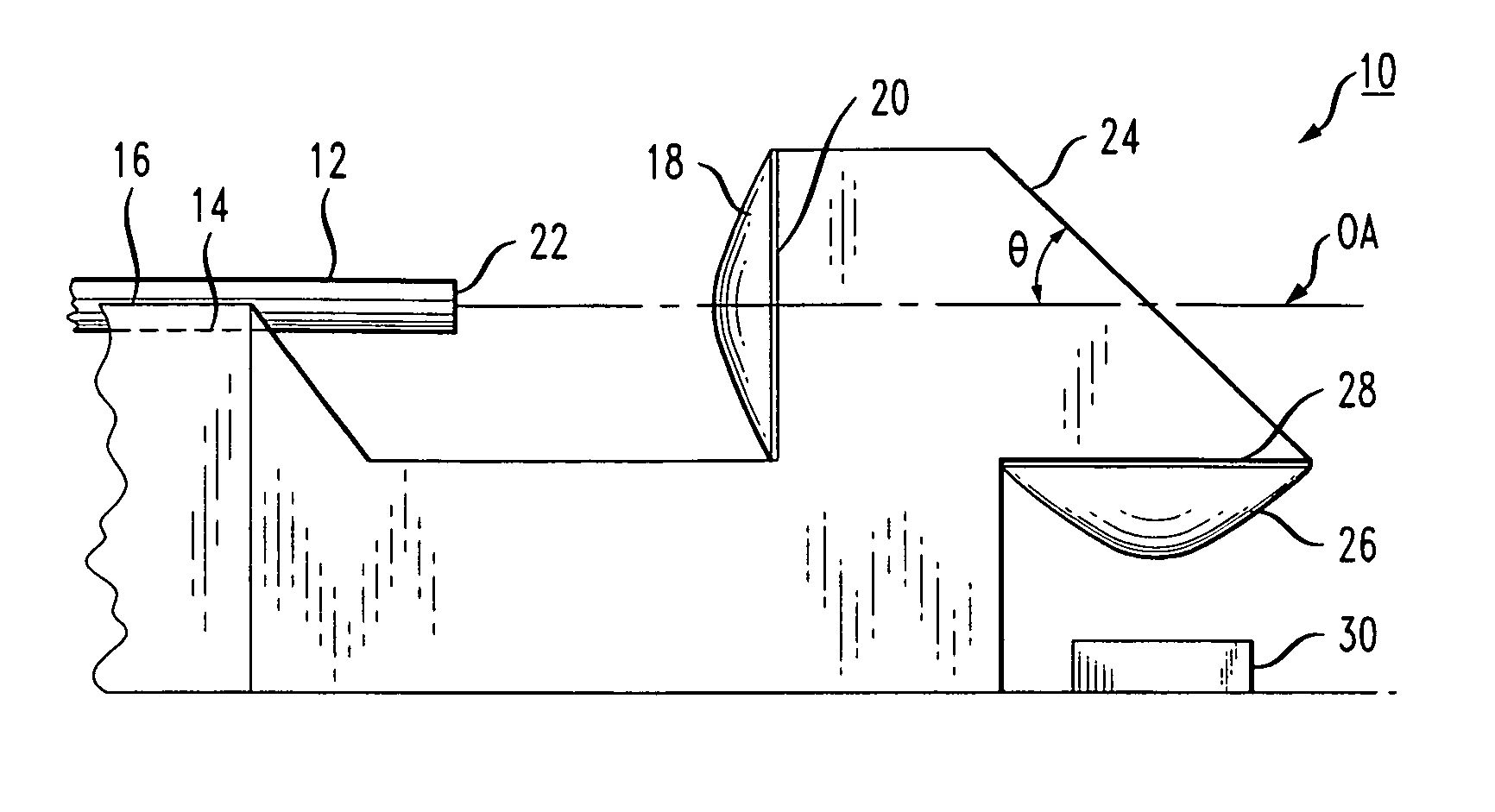
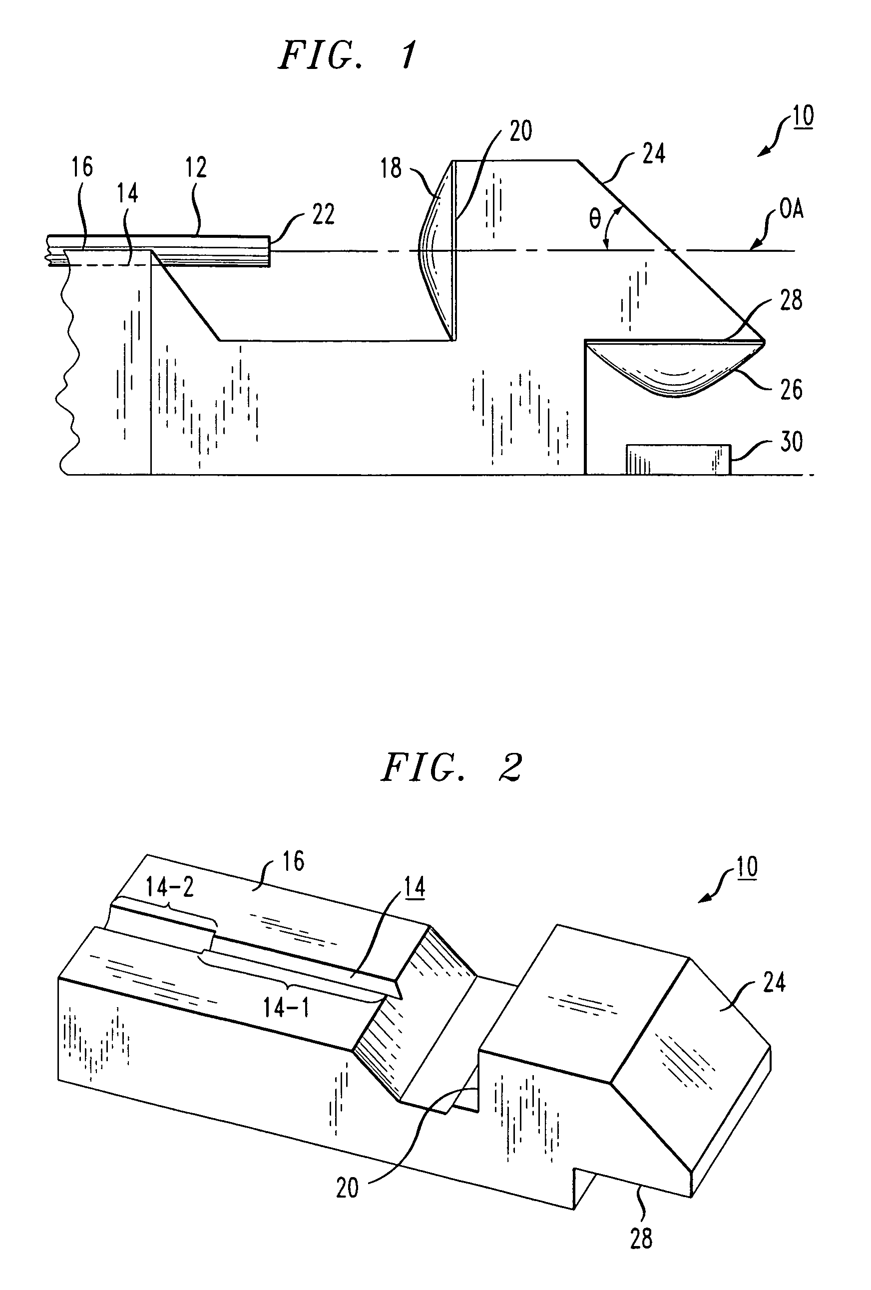
[0022]FIG. 1 illustrates an exemplary unitary optical receiver module 10 formed in accordance with the present invention. Module 10 is formed of a transparent material, such as a polyimide thermoplastic resin or any other material which allows for an optical signal to propagate therethrough with little or no loss of signal. An optical fiber 12, carrying the received optical signal, is disposed within a V-groove 14 formed in surface 16 of module 10.

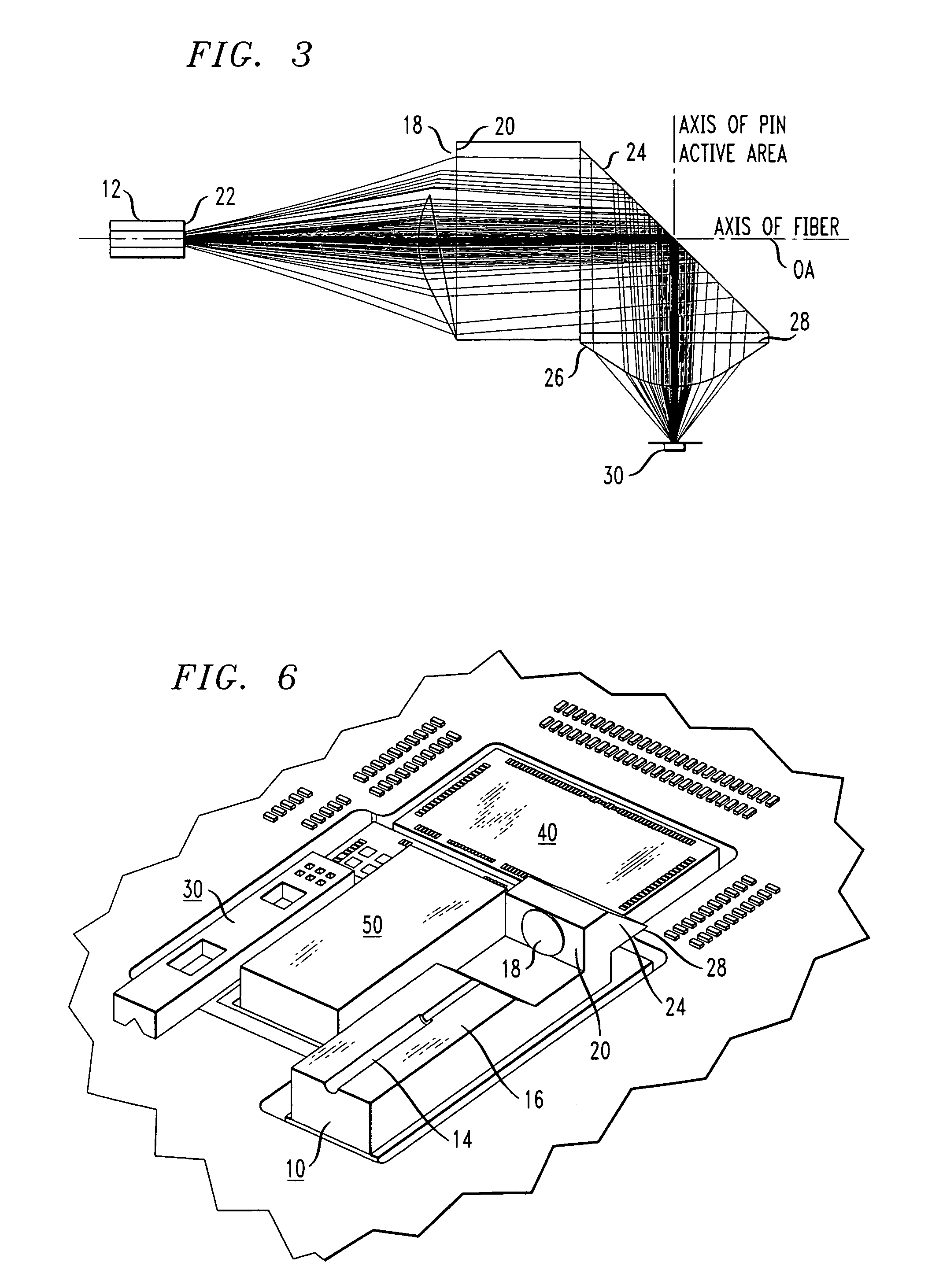
[0023]A collimating lens 18 is molded along a vertical wall 20 so as to align with the core region of optical fiber 12. Collimating lens 18 functions to capture the optical signal exiting endface 22 of fiber 12 and form a collimated wavefront which thereafter propagates through the transparent material of module 10. As shown in FIG. 1, the propagating signal will intercept angled wall 24 of module 10, where wall 24 is beveled at a predetermined angle θ with respect to the optical axis (OA). In a preferred embodiment, the angle θ may be 45°...


PUM


Abstract

A unitary optical receiver assembly is formed to include a V-groove passively aligned with a first aspheric lens (the lens formed along a surface perpendicular to the V-groove). An optical fiber is disposed along the V-groove and is used to bring the received optical signal into the unitary assembly. Upon passing through the first aspheric lens, the received optical signal will intercept a 45° turning mirror wall that directs the signal downward, through a second aspheric lens (also molded in the unitary assembly), and then into a photosensitive device. Advantageously, the photosensitive device is disposed in passive alignment with the second aspheric lens, allowing for a received signal to be coupled from an incoming optical fiber to a photosensitive device without needing any type of active alignment therebetween.

Description

CROSS-REFERENCE TO RELATED APPLICATIONS[0001]This application claims the benefit of U.S. Provisional Application No. 60 / 876,848, filed Dec. 22, 2006 and U.S. Provisional Application No. 60 / 899,208 filed Feb. 3, 2007.TECHNICAL FIELD[0002]The present invention relates to a dual-lensed unitary optical receiver assembly and, more particularly, to a unitary assembly for providing passive alignment between an incoming optical fiber (or other waveguiding structure) and a photosensitive receiving device.BACKGROUND OF THE INVENTION[0003]Optical networking, including fiber-optics and optoelectronics, is an important aspect of high speed communication systems, particularly for its ability to allow for efficient, accurate, and rapid transmission of data between various components in the network system. As with most communication systems, the efficient use of space and power in optical networks is of ever-increasing importance. Further, design considerations for such networks must take into acco...

Claims


Application Information

Patent Timeline
Patent Type & Authority Patents(United States)
IPC IPC(8): G02B6/32G02B6/34G02B6/42G02B6/43
CPCG02B6/4206G02B6/43G02B6/4214G02B6/28H04B10/00
Inventor BIRINCIOGLU, DINCERDIGHDE, RAJESHNADEAU, MARYPIEDE, DAVIDQIN, WENHONG
Owner CISCO TECH INC
Why Eureka
Try Eureka