

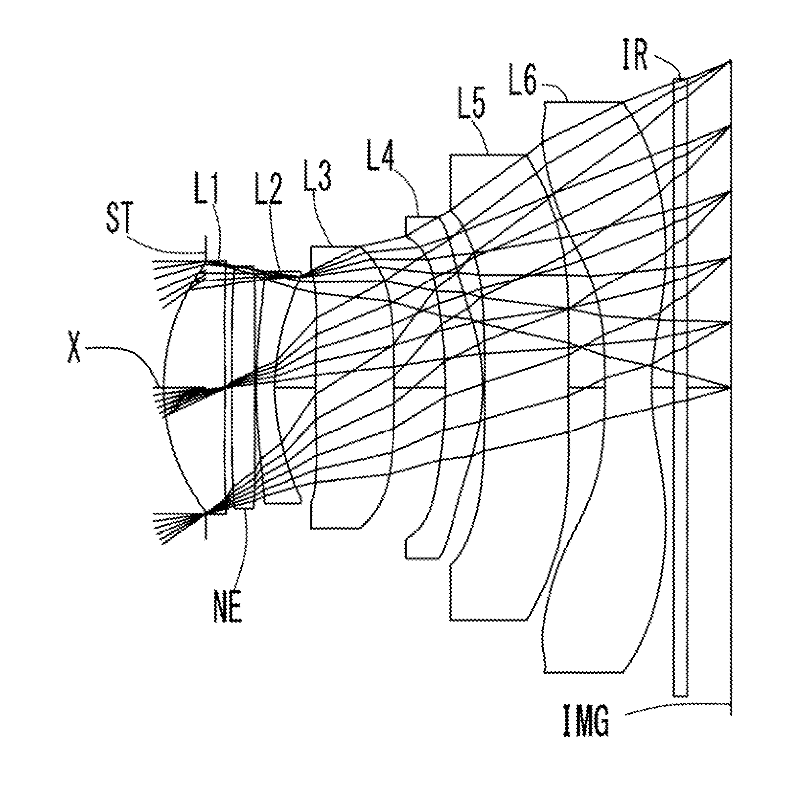
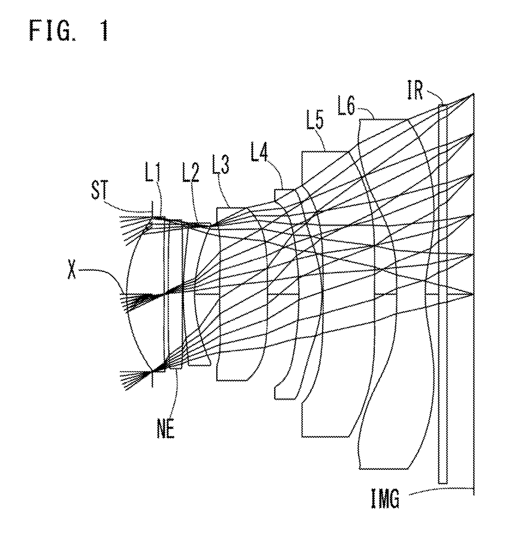
Imaging lens composed of seven optical elements
a technology of optical elements and imaging lenses, applied in the field of imaging lenses, can solve the problems of difficult to correct aberrations in the peripheral area properly, difficult to deliver high imaging performance throughout the image,
- Summary
- Abstract
- Description
- Claims
- Application Information
AI Technical Summary
Benefits of technology
Problems solved by technology
Method used
Image

Examples
numerical example 1
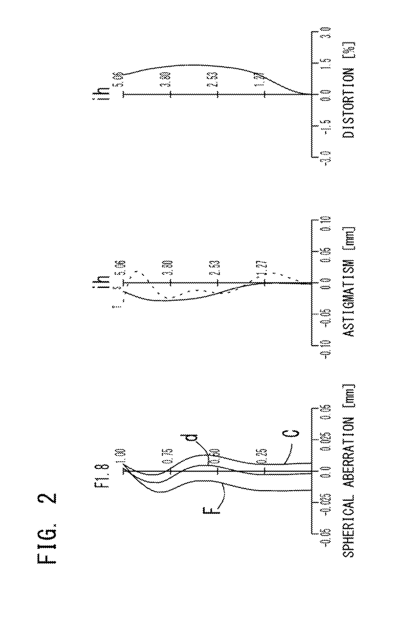
[0151]The basic lens data of Numerical Example 1 is shown below in Table 1.
TABLE 1Numerical Example 1in mmf = 7.03Fno = 1.8ω(°) = 35.5Surface DataSurfaceCurvatureSurfaceRefractiveAbbeNo. iRadius rDistance dIndex NdNumber ν d(Object Surface)InfinityInfinity1 (Stop)Infinity−0.646 2*3.1750.9431.54455.57(=ν d1) 3*−98.7290.109 4*Infinity0.3511.53555.66(=ν dN) 5*Infinity0.022 6*6.6030.2891.63923.25(=ν d2) 7*3.2160.631 8*19.7381.2161.53555.66(=ν d3) 9*−25.1720.79210*−8.0480.5801.53555.66(=ν d4)11*−3.2510.03012*−99.0001.2961.61425.58(=ν d5)13*99.0000.55914*−20.7960.7211.53555.66(=ν d6)15*3.5110.34016 Infinity0.2101.51764.2017 Infinity0.672Image PlaneInfinityConstituent Lens DataComposite Focal LengthLensStart SurfaceFocal LengthLensFocal Length125.681, 2, 37.5026−10.154, 511.113820.88Entrance Pupil Diameters 3.904109.78512−80.39614−5.56Aspheric Surface Data2nd Surface3rd Surface4th Surface5th Surface6th Surface7th Surface8th Surfacek0.000E+000.000E+000.000E+000.000E+000.000E+000.000E+000.00...
numerical example 2
[0155]The basic lens data of Numerical Example 2 is shown below in Table 2.
TABLE 2Numerical Example 2in mmf = 7.17Fno = 1.6ω(°) = 35.0Surface DataSurfaceCurvatureSurfaceRefractiveAbbeNo. iRadius rDistance dIndex NdNumber ν d(Object Surface)InfinityInfinity1 (Stop)Infinity−0.699 2*3.2451.1471.54455.57(=ν d1) 3*−99.0000.030 4*3.7920.3001.63523.97(=ν d2) 5*2.3230.686 6*20.0000.7011.53555.66(=ν d3) 7*−47.3340.368 8*Infinity0.8021.53555.66(=ν dN) 9*Infinity0.47510*−8.9490.6661.54455.57(=ν d4)11*−2.7320.03012*−19.0391.2191.61425.58(=ν d5)13*99.0000.52414*−99.0000.7231.53555.66(=ν d6)15*3.1890.34016 Infinity0.2101.51764.2017 Infinity0.801Image PlaneInfinityConstituent Lens DataComposite Focal LengthLensStart SurfaceFocal LengthLensFocal Length125.801, 2, 38.0724−10.254, 59.553626.38Entrance Pupil Diameter 4.384106.97512−25.90614−5.76Aspheric Surface Data2nd Surface3rd Surface4th Surface5th Surface6th Surface7th Surface8th Surfacek0.000E+000.000E+000.000E+000.000E+000.000E+000.000E+000.000E...
numerical example 3
[0159]The basic lens data of Numerical Example 3 is shown below in Table 3.
TABLE 3Numerical Example 3in mmf = 6.91Fno = 2.1ω(°) = 36.0Surface DataSurfaceCurvatureSurfaceRefractiveAbbeNo. iRadius rDistance dIndex NdNumber ν d(Object Surface)InfinityInfinity1 (Stop)Infinity−0.419 2*3.5710.7341.54455.57(=ν d1) 3*−37.3530.154 4*4.2850.4021.63523.97(=ν d2) 5*2.4520.732 6*15.0561.4981.53555.66(=ν d3) 7*−14.0220.773 8*−5.7260.8571.53555.66(=ν d4) 9*−2.0400.03010*−20.3530.7121.61425.58(=ν d5)11*32.3340.33412*20.5880.6771.53555.66(=ν d6)13*2.2870.35814*Infinity0.5671.53555.66(=ν dN)15*Infinity0.30016 Infinity0.2101.51764.2017 Infinity0.575Image PlaneInfinityConstituent Lens DataComposite Focal LengthLensStart SurfaceFocal LengthLensFocal Length126.031, 2, 37.2924−9.864, 57.563613.82Entrance Pupil Diameter 3.29485.48510−20.23612−4.87Aspheric Surface Data2nd Surface3rd Surface4th Surface5th Surface6th Surface7th Surface8th Surfacek0.000E+000.000E+000.000E+000.000E+000.000E+000.000E+000.000E+00...
PUM
 Abstract
Description
Claims
Application Information