Apparatus for locking accurate main shaft

A locking device and spindle technology, applied in metal processing equipment and other directions, can solve problems such as affecting the accuracy of the spindle, unreliable locking, and mechanical damage to the spindle, and achieve the effect of simple structure, guaranteed accuracy, and absolutely reliable locking.

Inactive Publication Date: 2009-05-20
GUANGZHOU CITY AGILE MFG
View PDF0 Cites 4 Cited by
  • Summary
  • Abstract
  • Description
  • Claims
  • Application Information

AI Technical Summary

Problems solved by technology

[0002] The existing machine tool spindle locking device has an eccentric error with the axis of the spindle during locking, causing mechanical damage to the spindle during locking, repeated locking and loosening for a long time, the mild one will affect the accuracy of the spindle bearing, and the severe one will damage the spindle Bearings, so it is easy to affect the accuracy of the spindle, and the locking is not reliable; and with the development of high-precision and high-speed machine tool technology, the accuracy and reliability requirements of the spindle are getting higher and higher. If the spindle locking device has an impact on the spindle accuracy , the machining accuracy cannot be reached, and the service life of the spindle bearing and the spindle will be reduced; in addition, the turn-milling compound machining center is becoming more and more popular now, and many processing parts need to be milled powerfully. The main shaft should not have any vibration, so the main shaft locking device is required to be absolutely reliable, and the existing locking device is difficult to meet the requirements

Method used


Image

  • Apparatus for locking accurate main shaft
  • Apparatus for locking accurate main shaft
  • Apparatus for locking accurate main shaft

Examples


Embodiment Construction

[0016] The present invention will be further described below in conjunction with accompanying drawing.

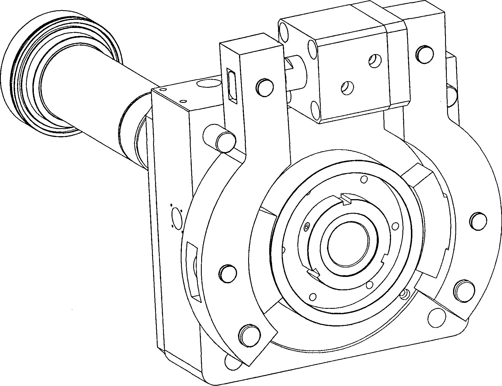
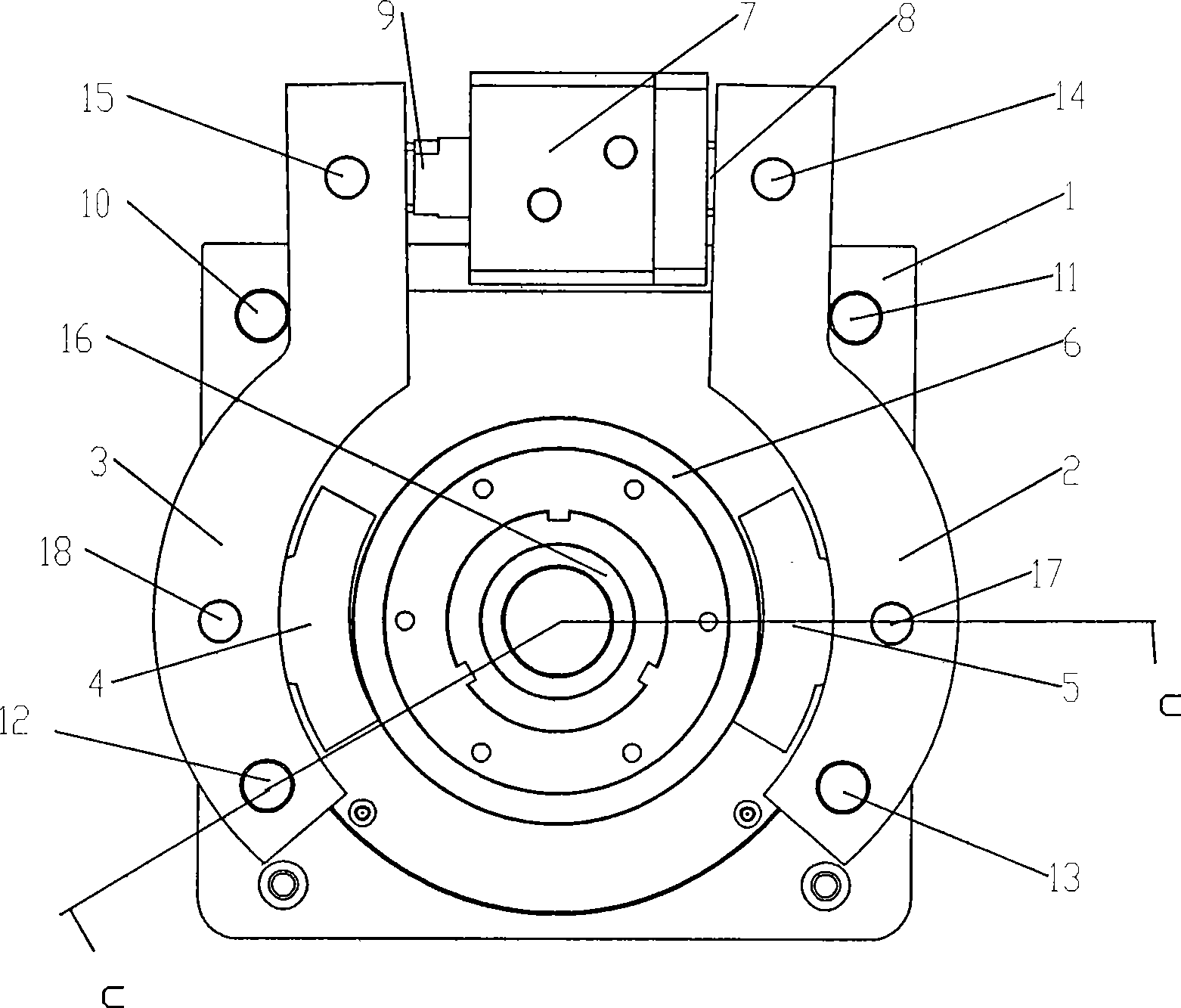
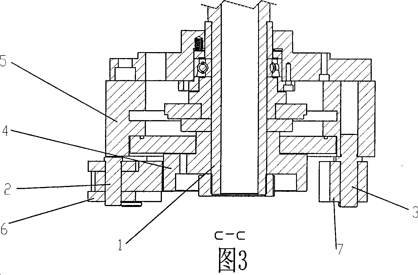
[0017] In the figure: fixed plate 1, right dowel bar 2, left dowel bar 3, left brake block 4, right brake block 5, flange plate 6, locking cylinder 7, right connecting rod 8, left connecting rod 9 , left blocking pin 10, right blocking pin 11, left rotating shaft 12, right rotating shaft 13, left connecting pin 14, right connecting pin 15, main shaft 16, right rotating pin 17, left rotating pin 18.

[0018] as attached figure 1 , attached figure 2 , as shown in accompanying drawing 3, a kind of precision main shaft locking device of the present invention, it is by fixing plate, flange plate, the brake block that is arranged symmetrically on both sides of flange plate, dowel, and locking oil cylinder The fixed plate 1 is fixed on the headstock, the lower part of the dowel bar is connected with the fixed plate, the right dowel bar 2 is connected with the fixed plate throug...


PUM


Abstract

The invention provides a precise spindle locking device and relates to a locking device. The locking device consists of a fixed board, a flange, braking blocks, dowel bars and a locking oil cylinder, wherein the braking blocks and the dowel bars are arranged at two sides of the flange and are bilaterally symmetric. The flange is fixed on a spindle. The fixed board is fixed on a spindle box. The dowel bars are fixed on the fixed board. The braking blocks are fixed on the inner sides of the dowel bars. The locking oil cylinder is fixed between the left and right dowel bars. Stop pins are arranged on the outer sides of the dowel bars. The dowel bars can rotate by taking only rotating shafts as centers. Braking blocks are fixed on the dowel bars through rotating pins. Based on principles of self-centering and lever force amplification, the precise spindle locking device avoids any influence on the precision of the spindle when the spindle is locked and absolutely reliable locking is achieved, thereby ensuring the precision of processed parts, the precision of the spindle and the service life of the spindle.

Description

technical field [0001] The precision spindle locking device of the present invention relates to a locking device, in particular to a precision spindle locking device. Background technique [0002] The existing machine tool spindle locking device has an eccentric error with the axis of the spindle during locking, causing mechanical damage to the spindle during locking, repeated locking and loosening for a long time, the mild one will affect the accuracy of the spindle bearing, and the severe one will damage the spindle Bearings, so it is easy to affect the accuracy of the spindle, and the locking is not reliable; and with the development of high-precision and high-speed machine tool technology, the accuracy and reliability requirements of the spindle are getting higher and higher. If the spindle locking device has an impact on the spindle accuracy , the machining accuracy cannot be reached, and the service life of the spindle bearing and the spindle will be reduced; in additi...

Claims


Application Information

Patent Timeline
Patent Type & Authority Applications(China)
IPC IPC(8): B23B19/02
Inventor 赵虎谢政平
Owner GUANGZHOU CITY AGILE MFG
Why Eureka
Try Eureka