Pile-forming equipment and method of control modulus pile

A technology of modulus pile and pile formation, which is used in the test of foundation structure, construction, foundation structure engineering, etc.

Inactive Publication Date: 2009-05-20
SOUTHEAST UNIV
View PDF0 Cites 5 Cited by
  • Summary
  • Abstract
  • Description
  • Claims
  • Application Information

AI Technical Summary

Problems solved by technology

Because of the great incompatibility of model piles and related equipment, related research and design can only be based on experience or existing engineering priors.

Method used


Image

  • Pile-forming equipment and method of control modulus pile
  • Pile-forming equipment and method of control modulus pile

Examples


Embodiment Construction

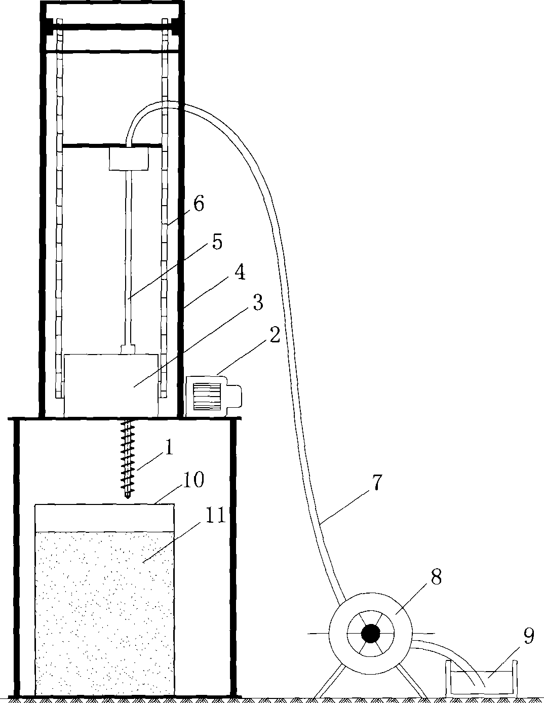
[0014] like figure 1 shown. A control modulus pile forming equipment, which consists of a drill bit 1, a motor 2, a control platform 3, a drill frame 4, a drill pipe 5, a transmission chain 6, a slurry delivery pipe 7, a pressurizing pump 8, and a model box 10, wherein the drill bit 1 and the drill pipe 5 are provided with longitudinal through holes, the output port of the booster pump 8 communicates with the upper through hole of the drill pipe 5 through the slurry delivery pipe 7, the lower part of the drill pipe 5 is set opposite to the upper part of the control platform 3, and the control platform 3 is fixed to the upper part of the drill frame 4, the upper part of the transmission chain 6 is respectively set opposite to the cross bar on the upper part of the drill frame 4, the lower part of the transmission chain 6 is respectively set opposite to the left and right ends of the control platform 3, and the motor 2 is fixed on the drill The upper part of the frame 4 and the...


PUM


Abstract

The invention discloses a pile-forming device and pile-forming method for control modulus pile, belonging to the field of bearing characteristic testing of composite foundation of geotechnical engineering. The device of the invention is composed of a drill bit, a motor, a control platform, a drill frame, a drilling rod, a driving chain, a slurry transporting pipe, a pressure pump, and a model box. The method of the invention includes the steps of filling simulation soil layer, preparing cement slurry, and forming pile. The invention realizes the quantitative design of control deform and control bearing force of the composite foundation, and fully mobilizes the function of the soil among piles by adjusting the stress ratio of the pile soil.

Description

technical field [0001] The invention relates to a control modulus pile forming equipment and a pile forming method, which belong to the field of testing the bearing characteristics of composite foundations in geotechnical engineering. Background technique [0002] Composite foundation is currently the most widely used soft soil foundation treatment method in the field of geotechnical engineering. Due to the complexity of foundation soil conditions, the current research on the mechanism of bearing characteristics of composite foundation is difficult to meet the requirements of actual engineering. Semi-empirical and semi-simplified quantification seriously restricts the in-depth development of composite foundation theory because pile formation and test equipment cannot meet the needs of research. Indoor tests are often carried out with model piles made of organic materials, and the test results are quite different from the actual monitoring results. Because of the great incom...

Claims


Application Information

Patent Timeline
Patent Type & Authority Applications(China)
IPC IPC(8): E02D33/00
Inventor 缪林昌赵马在宏蒋爱祥王非张亚军景春陈家富张成相
Owner SOUTHEAST UNIV
Why Eureka
Try Eureka