Hydraulic transformer for increasing voltage ratio regulation scope

A technology of hydraulic transformer and adjustment range, which is applied in the field of hydraulic transformer and can solve problems such as limited boosting capacity, transformer inoperability, communication, etc.

Inactive Publication Date: 2009-05-20
BEIJING INSTITUTE OF TECHNOLOGYGY
View PDF4 Cites 14 Cited by
  • Summary
  • Abstract
  • Description
  • Claims
  • Application Information

AI Technical Summary

Problems solved by technology

However, this change will also introduce another problem, that is, when the angle of the distribution plate changes, the contact area between the rear end surface of the distribution plate and the rear end cover will continue to change. The increasing thrust and decreasing supporting force lead to an increase in internal leakage of the transformer, a decrease in efficiency, and even communication between the slots, resulting in the failure of the transformer to work
Therefore, the maximum transformation ratio that this type of hydraulic transformer can achieve is small, and the boosting capacity is very limited, which limits the application range of this type of hydraulic transformer.

Method used


Image

  • Hydraulic transformer for increasing voltage ratio regulation scope
  • Hydraulic transformer for increasing voltage ratio regulation scope
  • Hydraulic transformer for increasing voltage ratio regulation scope

Examples


Embodiment Construction

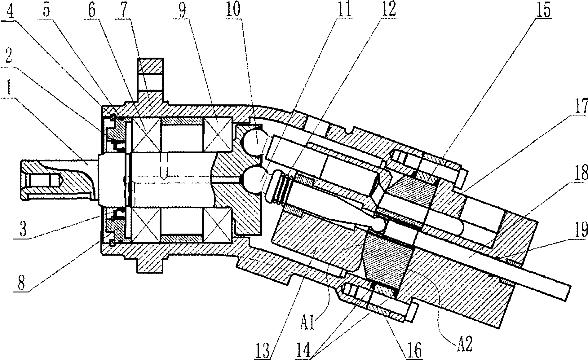
[0026] Below in conjunction with accompanying drawing and embodiment the present invention will be further described:

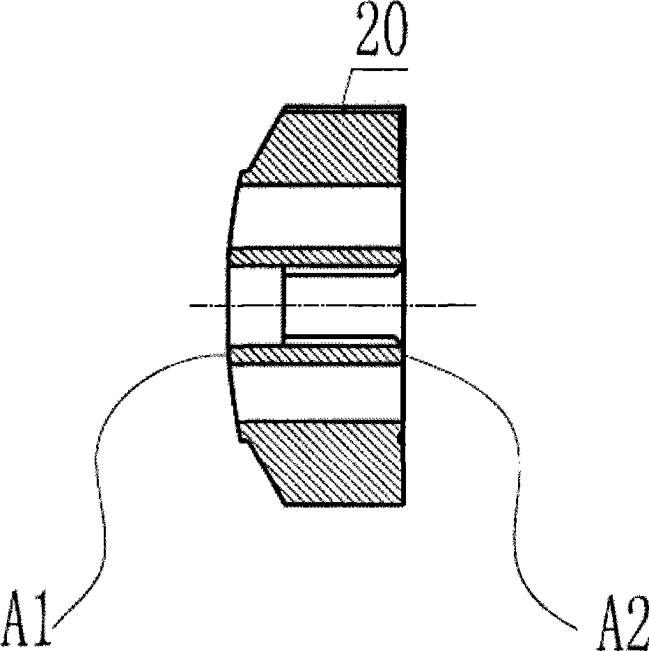
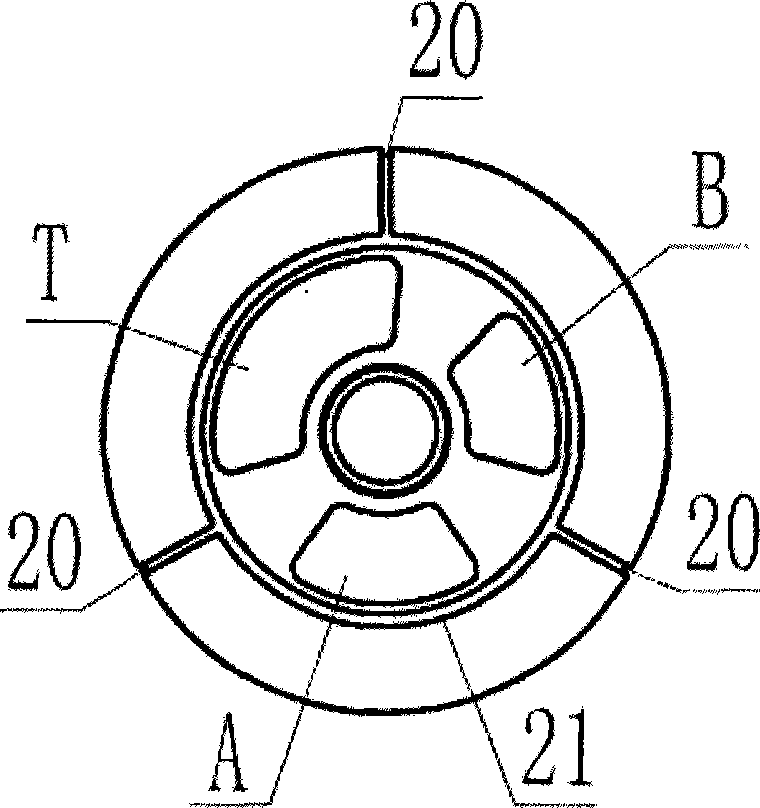
[0027] Such as figure 1 As shown, one end of the housing (7) fixes the front end cover (8) through the snap ring (4), and the O-ring (5) forms a seal, and the other end is connected with the transition plate (16) and the rear end cover (17) through 6 bolts. ) connection, the seal is formed by the O-ring (14), the main shaft (1) is installed in the housing (7) through the bearings (6), (9), and one end of the main shaft (1) and the front end cover (8) pass through the lip The sealing ring (3) forms a seal, the lip-shaped sealing ring (3) is fixed by the snap ring (2), one end of the central shaft (11) is hinged on the main shaft (1), and the other end passes through the center of the cylinder body (13). Installed in the copper sleeve at the center of the spherical end surface (A1) of the spherical distribution plate (15), the axis of the central shaft (11) in...


PUM


Abstract

The invention provides a hydraulic transformer capable of increasing the regulation range of transformation ratio. One end of a central shaft is hinged on a main shaft and the other end runs through a center of a cylinder body and is arranged in a copper sleeve at a center of a spherical end surface of a spherical valve plate. The spherical valve plate structure is adopted so that the spherical end surface of the spherical valve plate forms fit with the cylinder, and a rotating rod runs through the center of a rear end cover and is connected with the spherical valve plate through a spline. The spherical valve plate is made to rotate within a certain plus and minus angle range by rotating the rotating rod so as to adjust the transformation ratio. The spherical valve plate is designed to have a structure of notch wrap angle in different sizes, thereby realizing the purpose of changing transformation ratio in a wider range by the hydraulic transformer.

Description

technical field [0001] The invention relates to a hydraulic component, in particular to a hydraulic transformer which increases the adjustment range of the transformation ratio. Background technique [0002] As a new form of hydraulic system, the secondary regulation technology of constant pressure network can greatly improve the flexibility and efficiency of the hydraulic system. However, its application in the hydraulic field is currently limited, the main reason being that there is still a lack of an effective component for driving linear and rotary loads. Hydraulic transformers are developed under this technical background. [0003] Patent WO 97 / 31185 proposes a new hydraulic transformer design concept. Compared with traditional hydraulic transformers, this hydraulic transformer integrates the functions of hydraulic motor and hydraulic pump to form a single hydraulic component. Although the hydraulic transformer has many advantages in principle, many problems need to b...

Claims


Application Information

Patent Timeline
Patent Type & Authority Applications(China)
IPC IPC(8): F04B1/16F04B1/29F15B13/02
Inventor 胡纪滨苑士华荆崇波李小金魏超李雪原彭增雄
Owner BEIJING INSTITUTE OF TECHNOLOGYGY
Why Eureka
Try Eureka