High-frequency step-up transformer and progressive high-frequency step-up rectifying transformer

A step-up rectifier and transformer technology, which is applied in the fields of high-frequency step-up transformers and high-frequency step-up rectifier transformers, can solve the problems of reduced coupling efficiency of primary and secondary windings, insufficient maintenance of forward input excitation coupling, and reduced working efficiency of transformers. Transformer output efficiency, avoiding input return loss, maintaining reliability and stability

Inactive Publication Date: 2013-12-11
张继科
View PDF2 Cites 0 Cited by
  • Summary
  • Abstract
  • Description
  • Claims
  • Application Information

AI Technical Summary

Problems solved by technology

The reciprocating loop winding structure between multiple layers, the same-named end and the different-named end of the winding overlap between the layers, so that the induced electric field between the layers is offset and superimposed, and the coupling efficiency of the primary and secondary windings is reduced; in addition, there is insufficient maintenance of positive input excitation coupling , The technical problem of a large amount of coupling loss caused by instantaneous discharge during the reverse input return period also leads to a further decline in the working efficiency of the transformer
Due to the above factors, the voltage value of the high-voltage side is far from the theoretical value, the performance of the high-frequency transformer is extremely poor, the secondary winding, iron core and shielding layer are over-current and overheated, and the high-voltage output capability is low, which inhibits the high-voltage output capability

Method used


Image

  • High-frequency step-up transformer and progressive high-frequency step-up rectifying transformer
  • High-frequency step-up transformer and progressive high-frequency step-up rectifying transformer
  • High-frequency step-up transformer and progressive high-frequency step-up rectifying transformer

Examples


Embodiment Construction

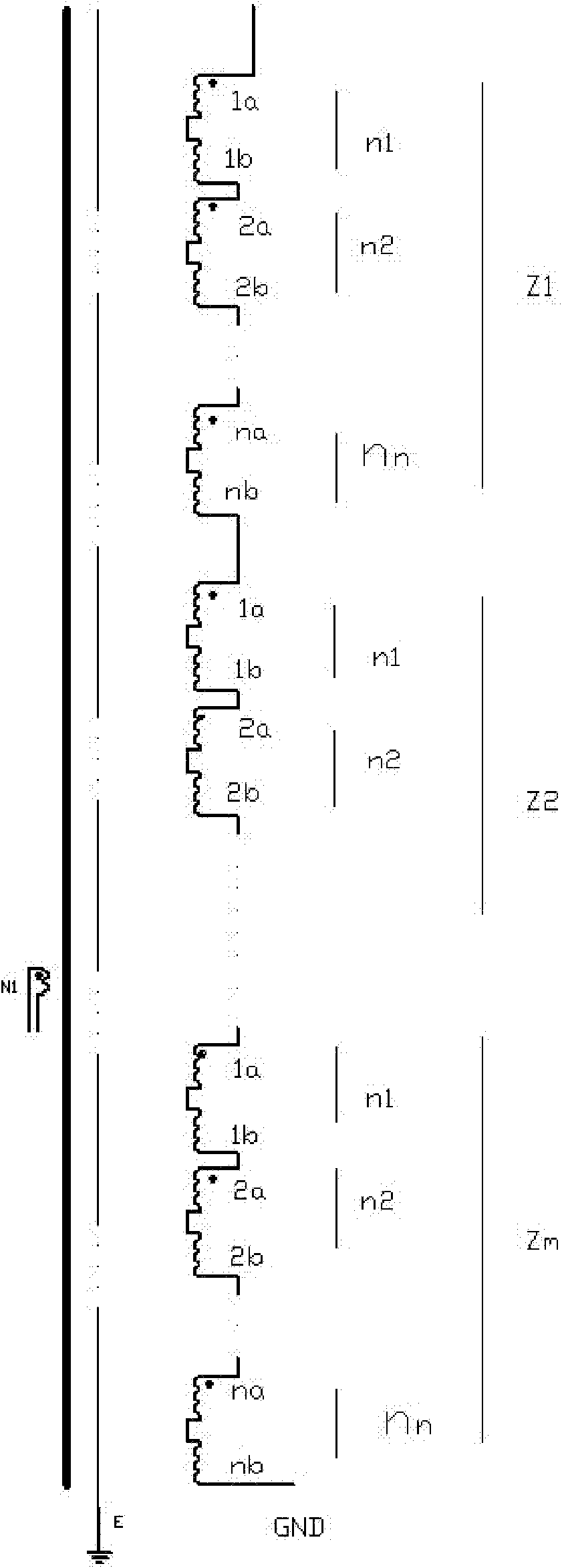
[0020] The high-frequency step-up transformer disclosed in the patent application of the present invention, such as figure 1 and Figure 9 , Figure 10 The structure shown in which the corresponding diodes and capacitors are connected is omitted, the primary winding N1 and the secondary winding N2 have the same end with the same name, the inner and outer layers are radially overlapped on the iron core 50 through the insulating shielding layer 52, and the secondary winding N2 includes: A number of winding segments that are insulated in the same direction as the primary winding and in the same direction as the helix, and are insulated sequentially along the axis of the iron core n .

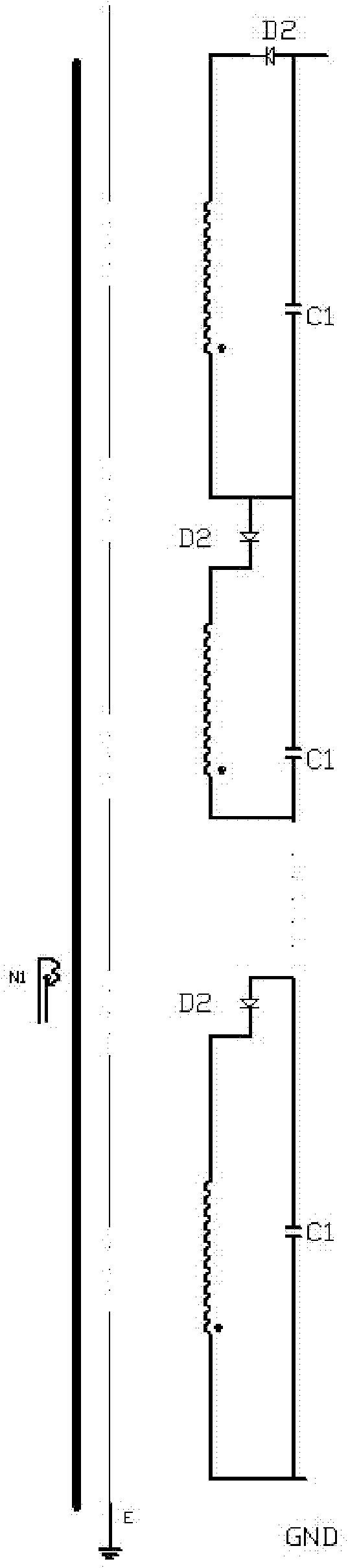
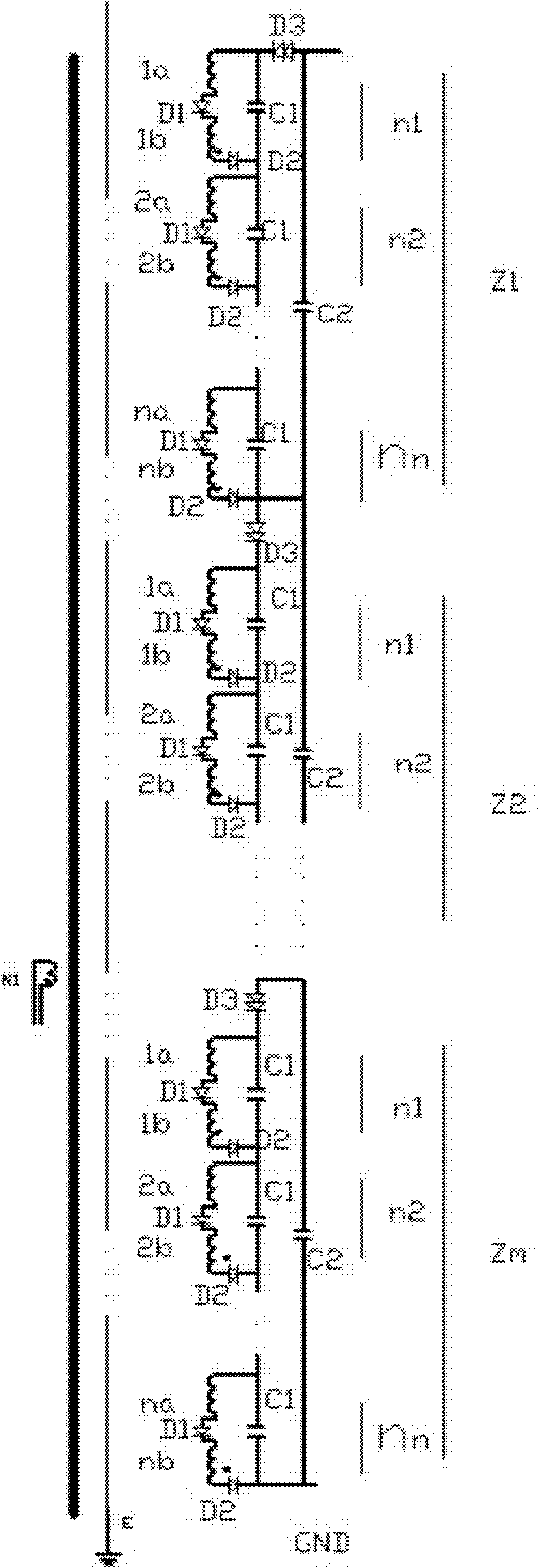
[0021] On the basis of the above-mentioned high-frequency step-up transformer, the present invention also provides a progressive high-frequency step-up rectifier transformer, such as figure 2 , image 3 , Figure 4 , Figure 5 as well as Figure 9 and Figure 10 As shown, it includes an ir...


PUM


Abstract

The invention provides a high-frequency step-up transformer. A primary winding and a secondary winding are arranged on an iron core in a mode that corresponding terminals are at the same end and inner and outer insulation shielding layers are radially overlapped; and the secondary winding comprises a plurality of winding sections which have the same winding direction and spiral direction as the primary winding and are coaxially sequentially arranged along an axis of the iron core in an insulating mode. Meanwhile, the invention provides a progressive high-frequency step-up rectifying transformer. A primary winding and a secondary winding of the progressive high-frequency step-up rectifying transformer have the same structure as the high-frequency step-up transformer, each winding section is connected in series with a fast recovery diode according to an excitation direction and is connected in parallel with a capacitor to form a winding loop unit; and a plurality of winding loop units are connected in series to form the secondary winding. The technical scheme has the advantages that the volume is small, the output efficiency of the transformer is high, high-voltage output is performed, and the reliability and stability of the high-voltage output are kept. High voltage and even extra-high voltage output work can be realized, and the output voltage is over one hundred thousand, hundreds of thousands and million volts.

Description

technical field [0001] The application of the present invention relates to a high-frequency step-up transformer and a high-frequency step-up rectifier transformer. Background technique [0002] The primary input adopts high-frequency signal to obtain secondary high-voltage output, so as to achieve the technical purpose of reducing the volume of the transformer to obtain high-voltage output, which is the original technical intention of scientific and technological personnel to launch high-frequency and high-voltage transformer products. High-frequency high-voltage transformers are widely used in various technical fields. The key technical problem faced by existing high-frequency transformers is how to weaken the adverse effects of the transformer's own distribution parameters, and what technicians pursue is to completely avoid the adverse effects of their own distribution parameters. However, the existence of transformer leakage inductance and distributed capacitance is unav...

Claims


Application Information

Patent Timeline
Patent Type & Authority Patents(China)
IPC IPC(8): H01F27/30H01F27/40H01F27/32H01F27/36
Inventor 张志鹏于艳张继科
Owner 张继科
Why Eureka
Try Eureka