Rotary transformer

A rotary transformer and rotary shaft technology, applied in transformers, inductors, magnetic circuit rotating parts and other directions, can solve the problems of low yield of steel workpieces, heavy rotor weight, and it is not easy to achieve lightweight rotary transformers, so as to prevent leakage. The effect of improving the magnetism and transformation ratio

Pending Publication Date: 2021-08-27
HONDA MOTOR CO LTD +1
View PDF8 Cites 0 Cited by
  • Summary
  • Abstract
  • Description
  • Claims
  • Application Information

AI Technical Summary

Problems solved by technology

[0003] In this case, there is a problem that the yield of the steel workpiece is low because a ring-shaped body with a predetermined diameter is punched out from the steel workpiece.
In addition, it is difficult to reduce the weight of the resolver because the rotor composed of a laminated body of electromagnetic steel sheets is heavy.

Method used


Image

  • Rotary transformer
  • Rotary transformer
  • Rotary transformer

Examples


Embodiment Construction

[0017] Hereinafter, preferred embodiments will be listed, and the resolver according to the present invention will be described in detail with reference to the drawings.

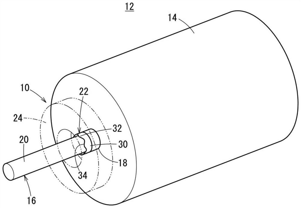
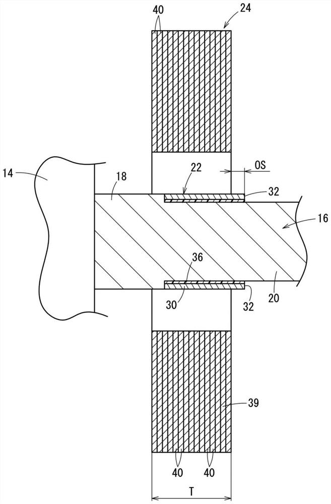
[0018] figure 1 is a schematic perspective view of main parts of a rotating electric machine 12 including the resolver 10 according to the present embodiment, figure 2 It is a schematic side sectional view of main parts of the resolver 10 . In this case, the rotary electric machine 12 is configured to include the resolver 10 and the motor 14 .

[0019] The rotary electric machine 12 includes a rotary shaft 16 as a structural component of the resolver 10 . The rotating shaft 16 has a short large-diameter portion 18 and a small-diameter portion 20 longer than the large-diameter portion 18 and smaller in diameter.

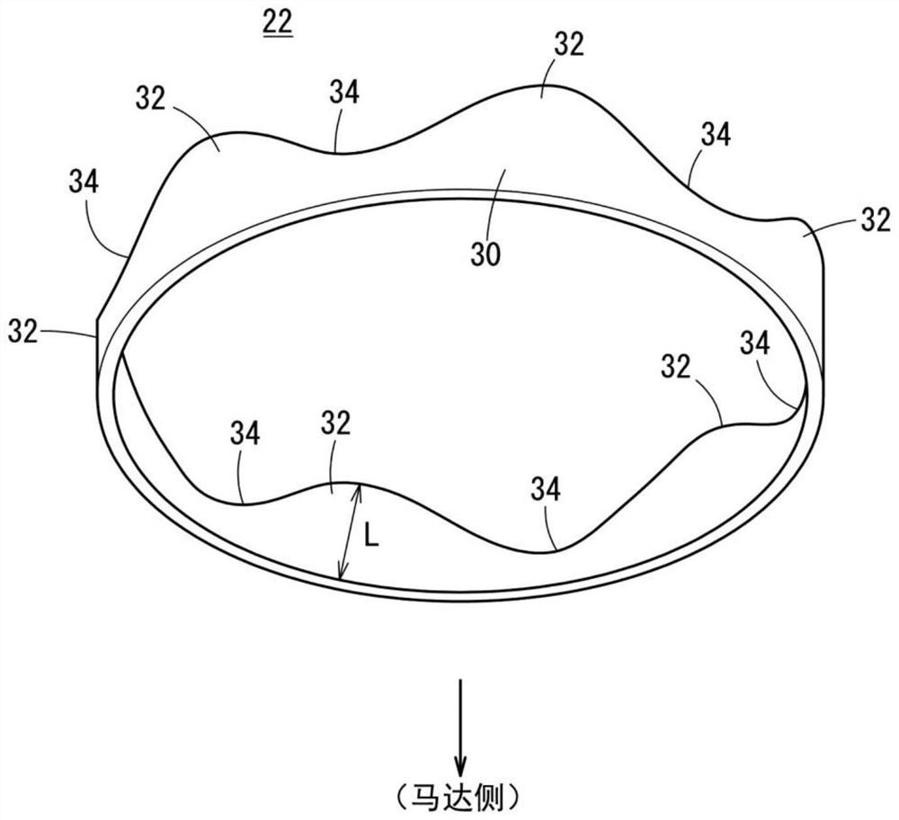
[0020] In addition, the resolver 10 has a resolver rotor 22 (rotor) assembled to the rotary shaft 16 , and a resolver stator 24 (stator) surrounding the resolver rotor 22 . The small-diameter p...


PUM


Abstract

The invention provides a rotary transformer. A rotary transformer rotor (22) provided to a rotating shaft (16) is configured from a single member having an annular portion (30), a convex portion (32) protruding in the axial direction of the rotating shaft (16), and a concave portion (34) integrally formed with the annular portion (30); the concave portion (34) is recessed with respect to the projection (32). An insulating layer (36) formed by coating or adhering is interposed between the rotary transformer rotor (22) and the rotating shaft (16).

Description

technical field [0001] The present invention relates to a resolver having a rotor provided on a rotating shaft and a stator surrounding the rotor. Background technique [0002] As a kind of angle sensor, a resolver constituted by a rotating electrical machine having a rotor provided on a rotating shaft constituting the rotating electrical machine and a stator surrounding the rotor is widely known. In a general resolver, as described in Japanese Patent Laid-Open Publication No. 2008-268065, the rotor is constructed by laminating thin electromagnetic steel sheets punched out of a steel workpiece into a ring shape by press forming. . [0003] In this case, since an annular body having a predetermined diameter is punched out from the steel workpiece, there is a disadvantage in that the yield of the steel workpiece is low. In addition, since a rotor made of a laminated body of electromagnetic steel sheets is heavy, it is difficult to reduce the weight of the resolver. Therefor...

Claims


Application Information

Patent Timeline
Patent Type & Authority Applications(China)
IPC IPC(8): H02K1/17H02K1/28H01F38/18
CPCH02K1/17H02K1/28H01F38/18H02K2213/03
Inventor 宫崎将吾关冨勇治今枝宏旨小木曾纪春山下重利
Owner HONDA MOTOR CO LTD
Why Eureka
Try Eureka