
Hydraulic Transformer Using Combined Valve Plate and Its Hydraulic Circuit

A hydraulic transformer, valve plate technology, applied in the direction of fluid pressure converter, fluid pressure actuating device, servo motor, etc., can solve problems such as no solution, vibration and noise valve plate, interface problems, etc., to improve displacement, The effect of reducing noise and cavitation, avoiding pressure surges

Active Publication Date: 2017-08-15
JINGDE COUNTY HANHAI NEBULA INTELLIGENTIZE TECH RES & DEV CO LTD
View PDF3 Cites 0 Cited by
  • Summary
  • Abstract
  • Description
  • Claims
  • Application Information

AI Technical Summary

Problems solved by technology

[0003] Rexroth company applied for the invention patent of DE10037114A1. In this patent, four waist-shaped grooves are arranged on the distribution plate of the hydraulic transformer, and the corresponding hydraulic circuit is specially designed. The hydraulic transformer cooperates with the designed hydraulic circuit to improve the voltage transformation to a certain extent However, the hydraulic transformer distribution still faces the "vibration and noise" and "interface problems between the valve plate and the rear end cover" described in "The Development Status of Hydraulic Transformers"
At present, there is still no good solution at home and abroad

Method used


Image

  • Hydraulic Transformer Using Combined Valve Plate and Its Hydraulic Circuit
  • Hydraulic Transformer Using Combined Valve Plate and Its Hydraulic Circuit
  • Hydraulic Transformer Using Combined Valve Plate and Its Hydraulic Circuit

Examples


Embodiment Construction

[0028] The present invention will be further described in detail below in conjunction with the drawings and embodiments.

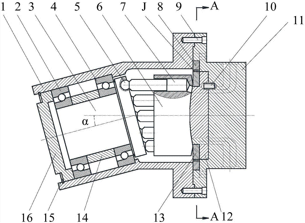
[0029] Such as figure 1 As shown, the front end cover 16, the front housing 1, and the rear housing 11 constitute a closed cavity of the inclined axis hydraulic transformer; the front end cover 16 has no opening hole, and the rotating shaft 3 is inside the closed cavity; the rotating shaft 3 passes The first bearing 2 and the second bearing 4 are installed in the central cavity of the front housing 1, the angle between the axis of the rotating shaft 3 and the axis of the plunger cylinder 6 is α=20°, the rotating shaft 3 and the plunger cylinder 6 rotate simultaneously During the process, the plunger 5 telescopically moves in the plunger cavity 7, and the plunger cavity realizes oil absorption and oil discharge;

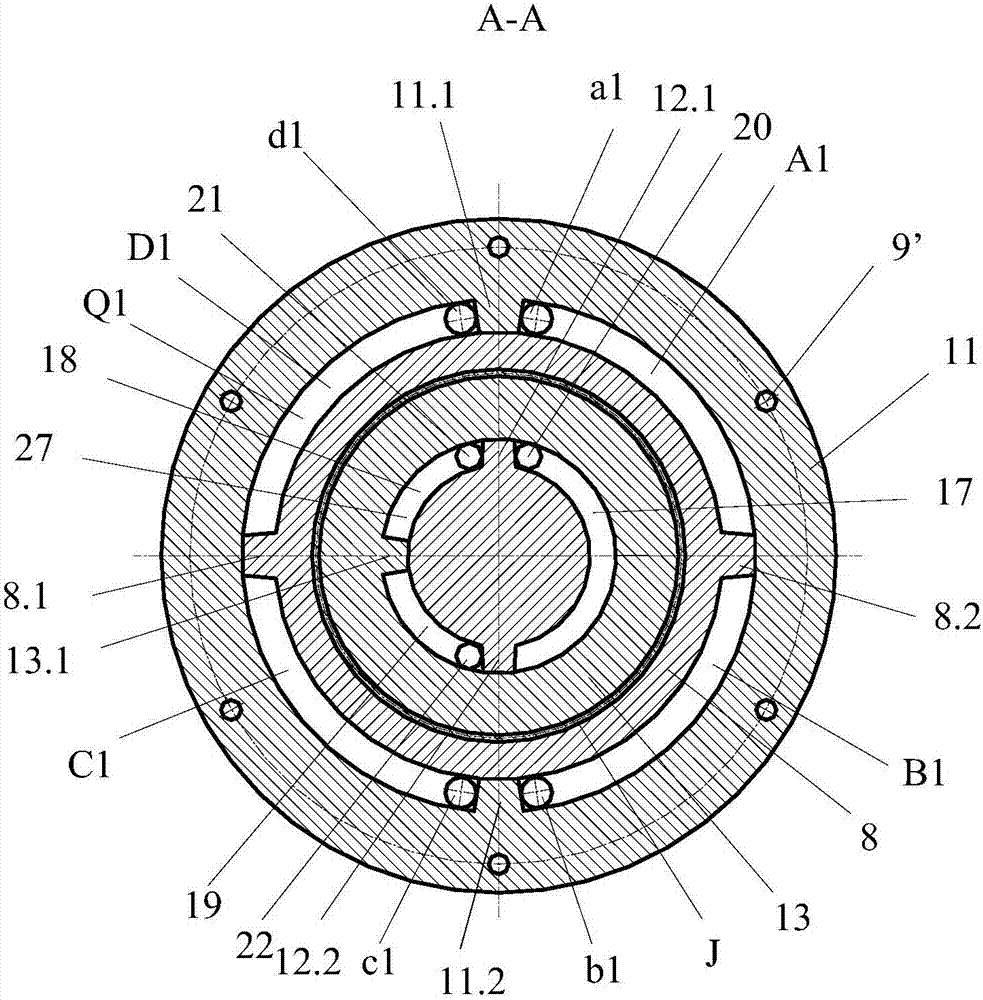
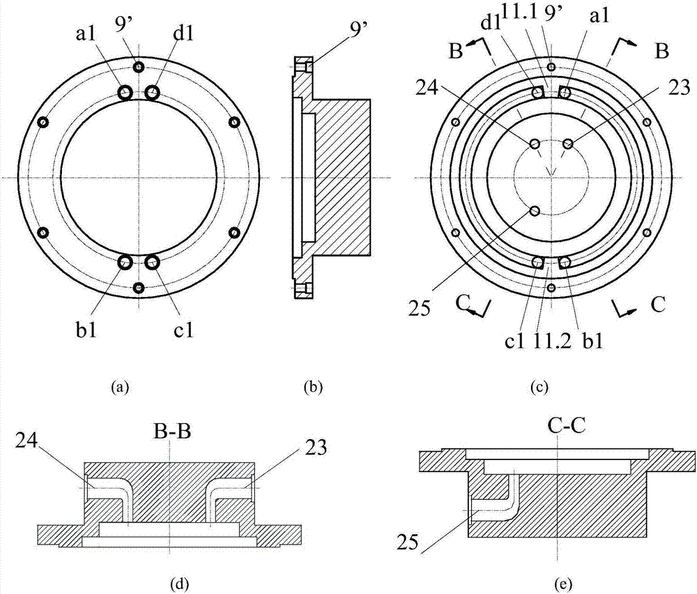
[0030] Such as figure 1 , 2 , 5 and 6, the inner plate 12 and the outer plate 13 together form a valve plate, which replaces the monolithic valve pl...


PUM


Abstract

The invention provides a hydraulic transformer adopting a combined type valve plate and a hydraulic circuit of the hydraulic transformer and belongs to the technical field of hydraulic pressure. The hydraulic transformer is characterized in that the outside of a boss of an inner disc manufactured with two external teeth is sleeved with an outer disc manufactured with an internal tooth, the right end surface of the outer disc and the left end surface of the base plate of the inner disc are attached, the internal tooth of the outer disc and the first external tooth and the second external tooth of the inner disc are located in one circular groove, the circular groove is cut into a first arc-shaped groove, a second arc-shaped groove and a third arc-shaped groove, a high pressure oil source is communicated with a plunger cavity through a first oil passage, a first oil hole and the first arc-shaped groove, an actuator is communicated with the plunger cavity through a second oil passage, a second oil hole and the second arc-shaped groove, a low pressure oil source is communicated with the plunger cavity through a third oil passage, a third oil hole and the third arc-shaped groove, the outer disc is driven by a swing motor rotor to rotate through a spline, and the inner disc is connected with a rear casing through a pin shaft. The hydraulic transformer adopting the combined type valve plate has the advantages that the structure of the valve plate of the hydraulic transformer is simple, a corresponding hydraulic circuit is matched so that the transformer ratio is effectively increased, vibration and noise are reduced, and servo control is easy to realize.

Description

Technical field [0001] The invention belongs to the technical field of hydraulic parts, and specifically relates to a hydraulic transformer and a hydraulic circuit using a combined valve plate. Background technique [0002] Constant pressure network secondary adjustment technology is a very important energy-saving solution in the field of hydraulic transmission today. The hydraulic transformer is the core component of the constant voltage network secondary regulation technology. Innas has applied for the WO9731185A1 invention patent. In this patent, the valve plate of the hydraulic transformer is evenly arranged with three waist-shaped grooves, which are respectively connected with a constant voltage source, a load and a low voltage source. The "Development Status of Hydraulic Transformers" summarized the technical problems existing in hydraulic transformers, namely "control problems", "vibration and noise", and "interface problems between the distributor plate and the rear cove...

Claims


Application Information

Patent Timeline
Patent Type & Authority Patents(China)
IPC IPC(8): F15B3/00F15B11/08
CPCF15B3/00F15B11/08
Inventor 仉志强李永堂刘志奇贾跃虎宋建丽
Owner JINGDE COUNTY HANHAI NEBULA INTELLIGENTIZE TECH RES & DEV CO LTD
Learn More