Automatic charger of traction accumulator

A traction battery and automatic charging technology, which is applied to battery circuit devices, electric vehicles, and energy-saving charging equipment, etc., can solve the problems that the performance of the charger does not meet the battery charging, does not meet the battery charging requirements, and reduces the service life of the battery. Achieve the effect of reducing resource utilization, less heat generation and prolonging the service life of the battery

Active Publication Date: 2009-01-14
ZIBO TORCH ENERGY
View PDF0 Cites 9 Cited by
  • Summary
  • Abstract
  • Description
  • Claims
  • Application Information

AI Technical Summary

Problems solved by technology

Some existing chargers can only perform simple charging operations, and manual adjustments are required during the charging process. If you do not understand the charging technology, you will not be able to use the battery properly, or even explode if you do not operate properly.
Although another type of charger is known as an intelligent charger, due to the lack of thorough understanding of battery charging technology, the performance of the charger does not meet the requirements of battery charging, resulting in undercharging or overcharging of the battery, which is easy to damage the battery and greatly reduces the battery life. battery life
Such a charger does not meet the charging requirements of the battery

Method used


Image

  • Automatic charger of traction accumulator
  • Automatic charger of traction accumulator
  • Automatic charger of traction accumulator

Examples


Embodiment Construction

[0020] Embodiments of the present invention will be further described below according to the accompanying drawings:

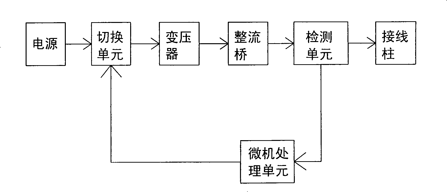
[0021] Such as figure 1 As shown, the primary side of the transformer is connected to the main line of the power supply, the secondary side is connected to the input terminal of the rectifier bridge, and the output terminal of the rectifier bridge is connected to the binding post. The detection unit is arranged on the output end of the rectifier bridge and the wire of the binding post, the output end of the detection unit is connected to the input end of the microcomputer processing unit, and the output end of the microcomputer processing unit is connected to the input end of the switching unit. The switching unit is arranged on the main wire of the power supply and the wire on the primary side of the transformer.

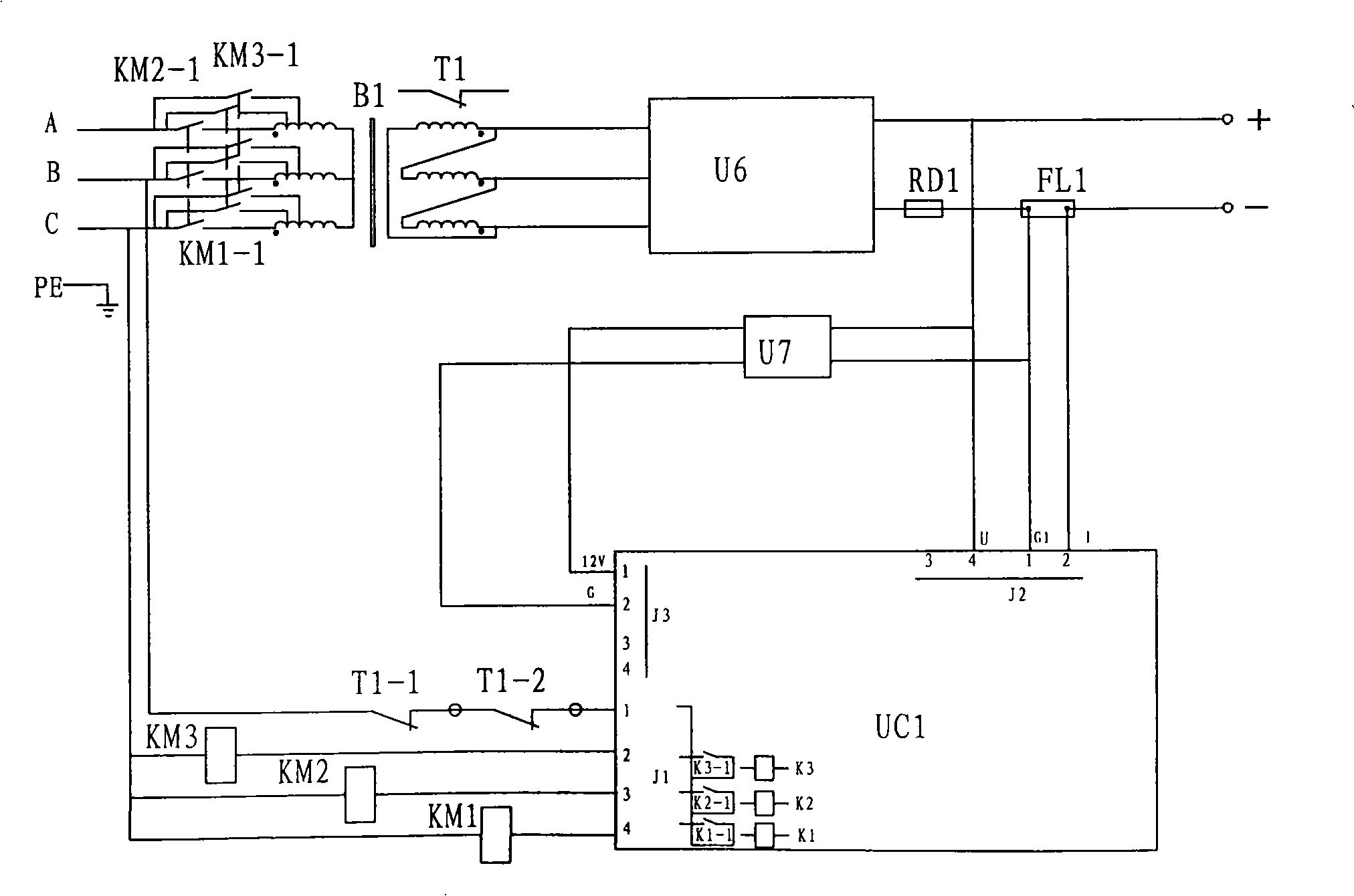
[0022] A fuse protector ( figure 2 shown).

[0023] The microcomputer processing unit, the detection unit and the switching unit form a detecti...


PUM


Abstract

The invention discloses a traction battery automatic charger comprising a transformer and a rectifier bridge. The primary side of the transformer is connected to a power main line, the secondary side is connected to the input end of the rectifier bridge and the output end of the rectifier bridge is connected to a terminal through a fusing protector. The main technical characteristics is that a plurality of regulation taps are arranged on the primary side of the transformer, a detection and control module is formed by a detection unit, a microcomputer processing unit and a switching unit, wherein the detection unit includes a voltage sensor, a current sensor and a temperature sensor, the output end of the detection unit is connected to the input end of the microcomputer processing unit, the output end of the microcomputer processing unit is connected to the input end of the switching unit, the switching unit is correspondingly arranged between the power main line and each regulation tap at primary side of the transformer. The charger intellectualization is achieved according to the invention and the charge process is finished in shortest time with highest efficiency and unattended duty. The battery life is prolonged because of the least heat generation and water loss of the battery during the charge process.

Description

Technical field: [0001] The invention relates to an automatic charger for traction batteries, which belongs to the field of automatic charging devices for lead-acid batteries. Background technique: [0002] The storage battery is a secondary battery, which can be charged and used many times by a charger. But charging the battery requires certain expertise. During the use of lead-acid battery packs, due to various reasons, the active substances on individual battery plates will not be recovered in time, and the parameters of the batteries will be unbalanced. This affects the capacity and life of the storage battery pack, reducing the use value of the entire battery pack. Therefore, it is necessary to carry out equalization charging to the battery pack at regular intervals. Some existing chargers can only perform simple charging operations, and human adjustment is required during the charging process. If you do not understand the charging technology, you will not be able to...

Claims


Application Information

Patent Timeline
Patent Type & Authority Applications(China)
IPC IPC(8): H02J7/00
CPCY02E70/40Y02E60/10
Inventor 王培寿聂斌潘伟伟李宝军郭方营
Owner ZIBO TORCH ENERGY
Why Eureka
Try Eureka