Gas turbine combined type fuel evaporating and atomizing combustion apparatus

A fuel atomization and combustion device technology, applied in combustion chambers, combustion methods, combustion equipment, etc., can solve the problems of no fuel primary atomization premixing pre-evaporation process, poor fuel atomization of direct injection nozzles, easy coke accumulation, etc. , to achieve the effect of improving fuel atomization evaporation and blending performance, improving the uniformity of oil-gas spatial distribution, and increasing the gas-phase oil-gas ratio

Inactive Publication Date: 2009-05-20
PEKING UNIV
View PDF0 Cites 29 Cited by
  • Summary
  • Abstract
  • Description
  • Claims
  • Application Information

AI Technical Summary

Problems solved by technology

[0004] ① Poor fuel atomization of direct injection nozzle, small spray cone angle and narrow working range
[0005] ②The centrifugal nozzle has good atomization quality, reasonable oil mist distribution, good ignition performance and wide stable combustion range, but it is prone to smoke under high pressure and easy to accumulate coke under high temperature
[0006] ③Fuel and air pre-mixing, pre-evaporation, low NO x Divergent, no exhaust smoke, relatively stable combustion performance and temperature distribution, but there are dangers of automatic ignition, backfire, and flameout, narrow stable combustion range, and poor reliability at high temperatures
[0009] Among them, the ④ and ⑤ nozzles are currently advanced fuel atomization technologies, but there is no primary atomization premixing and pre-evaporation process of fuel, and the liquid film space distribution is narrow. Fuel atomization and gradual mixing with air are completed in the combustion chamber. Existence of liquid mist combustion and higher NO x emission

Method used


Image

  • Gas turbine combined type fuel evaporating and atomizing combustion apparatus
  • Gas turbine combined type fuel evaporating and atomizing combustion apparatus
  • Gas turbine combined type fuel evaporating and atomizing combustion apparatus

Examples


Embodiment 1

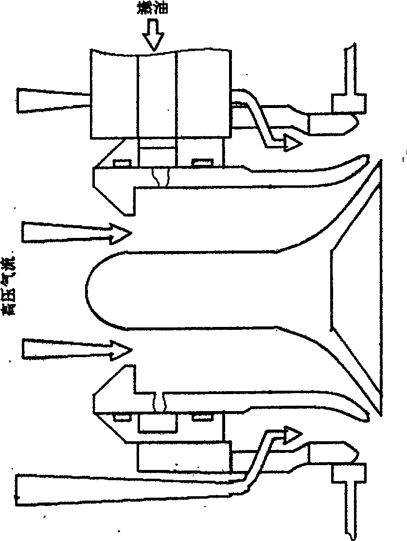
[0057] A combined fuel atomization device for a gas turbine, comprising a nozzle 1, a premixing chamber 2, an evaporator 3, a double swirler 4, a centrifugal nozzle 5, a venturi tube 6, a sleeve 7 and a combustion chamber 8.

[0058] The nozzle 1 refers to the fuel centrifugal spray group or other nozzles (such as atomizing tank nozzles), which are installed at the center of the inlet of the premix chamber 2; A straight pipe with the same diameter, it is in the upstream of the double cyclone 4, and is sealed with the outer end of the double cyclone 4; the evaporator 3 refers to a plurality of thin steel pipes welded in parallel (or a plurality of round pipes set or blunt body, etc.), installed inside the premixing chamber 2, a certain distance upstream is the nozzle, and a certain distance downstream is the double cyclone 4; Composed of cyclones, each cyclone has multiple blades, the inlet and outlet are straight sections, and the middle is connected by an arc. It is installed...

Embodiment 2

[0061] A gas turbine combined fuel atomization evaporation combustion device, including a nozzle 1, a premixing chamber 2, an evaporator 3, an axial swirler 12, a centrifugal nozzle 5, a venturi tube 6, a fixed seat 7, and a radial swirler 8. It is composed of connecting plate 9, sleeve 10 and combustion chamber 11.

[0062] The nozzle 1 refers to the fuel centrifugal spray group or other nozzles (such as atomization tank nozzles), which are installed at the center of the inlet of the premix chamber 2; the premix chamber 2 refers to the 4 straight pipes with the same outer diameter, which are in the upstream of the axial swirler 12 and sealed with the inlet outer end of the axial swirler 12; the evaporator 3 refers to double blunt bodies (or spiral bodies or multiple Thin steel pipes are welded side by side or a plurality of round pipes are set), installed inside the premixing chamber 2, a certain distance upstream is the nozzle, and a certain distance downstream is the axial ...

Embodiment 3

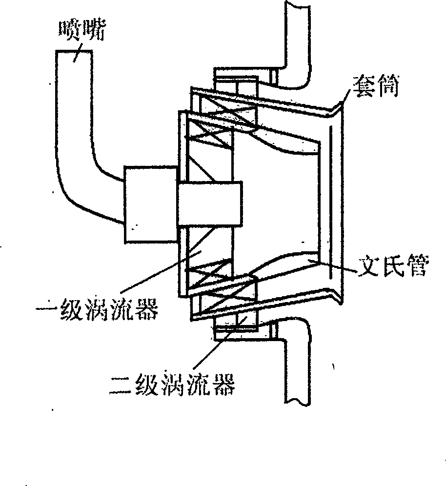
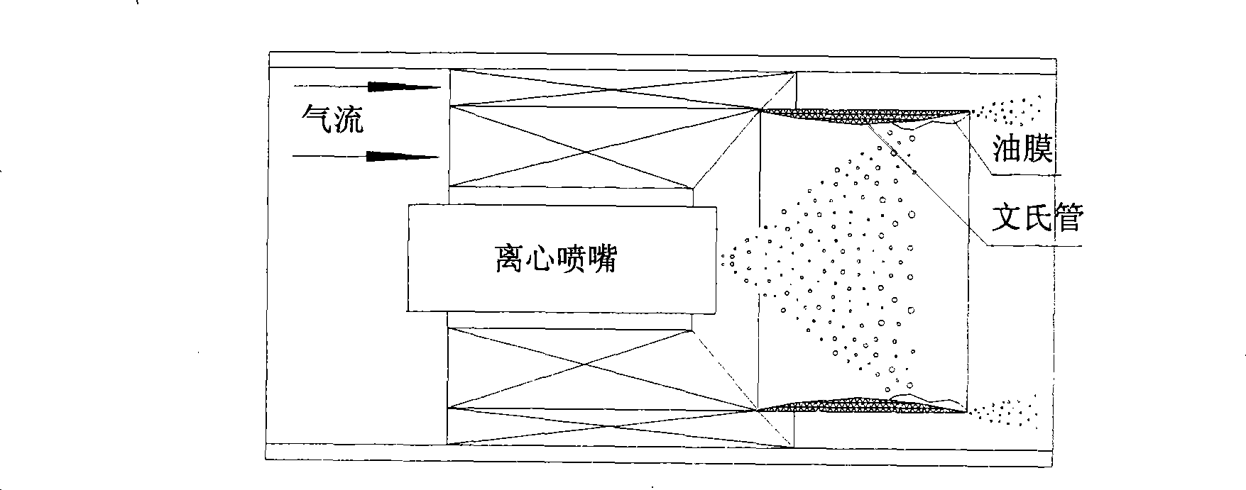
[0064] Embodiment 3: as Figure 5 Shown is a structural schematic diagram of the first scheme of the gas turbine combined fuel atomization evaporation combustion device. It consists of a nozzle 1, a premix chamber 2, an evaporator 3, a double swirler 4, a centrifugal nozzle 5, a venturi tube 6, a sleeve 7 and a combustion chamber 8. The nozzle 1 is installed at the center of the inlet of the pre-mixing chamber 2; Sealed connection; the evaporator 3 is installed inside the premixing chamber 2, the nozzle is a certain distance upstream, and the double cyclone 4 is a certain distance downstream; the double cyclone 4 is installed inside the outlet end of the premixing chamber 2, and is connected with the premixing The chamber 2 is tightly connected, and the centrifugal nozzle 5 is installed at the center of the double swirler 4; the venturi tube 6 is welded at the outlet of the inner and outer swirlers of the double swirler 4, upstream of the combustion chamber 8; the inner side ...


PUM


Abstract

The invention provides a combined fuel oil atomizing, evaporating and combusting device for a gas turbine, relates to an air inlet device of the gas turbine, a fuel oil atomizing, evaporating and blending device, and core technology of organized combustion and stable flame, and belongs to the power field of an aeronautic power propulsion system and a ground gas turbine. A nozzle 1 is arranged at a central position of an inlet of a premixing chamber 2; an evaporator 3 is fixed in an inner cavity of the premixing chamber 2; double cyclones 4 are arranged at the inside of the outlet end of the premixing chamber 2 and connected hermetically; a centrifugal nozzle 5 is arranged at a central position of the double cyclones 4; a venturi 6 is welded at a transition position of an outlet of internal and external cyclones of the double cyclones 4; a sleeve 7 is hermetically welded with the outside of an outlet of the premixing chamber 2; and the head of a combustion chamber 8 is hermetically welded with the sleeve 7. Compared with the prior fuel oil combined nozzle, the device has the advantages of improving properties of fuel oil atomizing, evaporating and blending and evenness of oil-gas space distribution, improving combustion performance, shortening flame length and reducing discharge of pollutant, and is a comparatively ideal combined fuel oil atomizing and combusting device for a high-performance gas turbine.

Description

technical field [0001] The invention relates to a gas turbine combined fuel atomization, evaporation, and combustion device, a combined fuel atomization, evaporation, and combustion device used by aviation and ground gas turbines, which belongs to a gas turbine air intake device, a fuel atomization, evaporation and mixing device, The core technology of organizing combustion and stabilizing the flame belongs to the field of aerodynamic propulsion system and ground gas turbine power. Background technique [0002] At present, the fuel nozzles in gas turbine power plants at home and abroad mostly use liquid film air atomizing nozzles and combined air atomizing devices. With the development of high-performance engines, it is required to complete combustion in a shorter combustion zone, shorten the length of the combustion chamber, reduce weight, better organize the concentration field of fuel, higher requirements for ignition performance and lean flameout range, lower pollutant ...

Claims


Application Information

Patent Timeline
Patent Type & Authority Applications(China)
IPC IPC(8): F23R3/30
Inventor 郑殿峰
Owner PEKING UNIV
Why Eureka
Try Eureka