
Suction type two-stage shock wave focusing ignition engine combustion chamber and working method thereof

A shock-focusing and combustion chamber technology, which is applied to machines/engines, gas turbines, mechanical equipment, etc., can solve the problem that PDE cannot achieve controllable and stable ignition of high-frequency shock-focusing ignition, and achieve controllable and stable ignition. Ignition, the effect of overcoming the high frequency unstable shock focus ignition problem, and the effect of overcoming the shock focus attenuation problem

Active Publication Date: 2019-11-05
HUAZHONG UNIV OF SCI & TECH
View PDF6 Cites 7 Cited by
  • Summary
  • Abstract
  • Description
  • Claims
  • Application Information

AI Technical Summary

Problems solved by technology

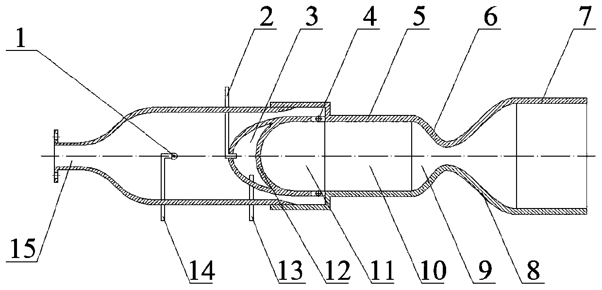
[0006] Aiming at the above defects or improvement needs of the prior art, the present invention provides an air-breathing two-stage shock-wave focusing ignition engine combustion chamber and its working method. The combination of shock wave focused ignition and shock wave concave cavity reflection focused ignition can realize the detonation of the detonation chamber of the pulse detonation engine in a short distance, thus solving the problem that the existing PDE cannot realize the controllable and stable ignition of the high frequency shock wave focused ignition technical problem

Method used


Image

  • Suction type two-stage shock wave focusing ignition engine combustion chamber and working method thereof
  • Suction type two-stage shock wave focusing ignition engine combustion chamber and working method thereof

Examples


Embodiment Construction

[0050] In order to make the object, technical solution and advantages of the present invention clearer, the present invention will be further described in detail below in conjunction with the accompanying drawings and embodiments. It should be understood that the specific embodiments described here are only used to explain the present invention, not to limit the present invention. In addition, the technical features involved in the various embodiments of the present invention described below can be combined with each other as long as they do not constitute a conflict with each other.

[0051] In describing the present invention, it is to be understood that the terms "center", "upper", "lower", "front", "rear", "left", "right", "vertical", "horizontal", The orientations or positional relationships indicated by "top", "bottom", "inner", "outer", etc. are based on the orientations or positional relationships shown in the drawings, and are only for the convenience of describing th...


PUM


Abstract

The invention discloses a suction type two-stage shock wave focusing ignition engine combustion chamber and a working method thereof, and belongs to the technical field of detonation engines. The combustion chamber comprises a first cavity body, a first combustion chamber shell, a first shock wave focusing concave surface, two rotating valve flaps, a pre-cooling chamber concave surface, a second shock wave focusing concave surface, a divergent section, a second combustion chamber cavity body, a cold oil pipe, a first heat oil pipe, a second heat pipe and a rotary fuel atomization nozzle. By rotating the rotating valve flaps, intermittent jet flow of air is controlled, so that intermittent shock wave focusing ignition detonating mixed combustible gas in a shock wave focusing chamber is realized, and the reliability of detonation of the engine combustion chamber is further improved through the forward and reverse arranged two-stage shock wave focusing concave cavities. According to the combustion chamber and the working method, the combustion chamber can stably realize high-frequency shock-wave-focused ignition while axially air sucking like a traditional engine, the engine combustion chamber quality is effectively improved, the thrust performance of the engine is improved, and a new technical way is provided for developing a practical high-power detonation engine.

Description

technical field [0001] The invention belongs to the technical field of detonation engines, and more specifically relates to an air-breathing two-stage shock wave focusing ignition engine combustion chamber and a working method thereof. Background technique [0002] The pulse detonation engine (PDE) has the advantages of high cycle thermal efficiency, compact and simple structure, and high specific impulse. In the low-frequency working mode, PDE cannot produce continuous effective thrust. For this reason, people have developed a variety of multi-tube coordinated linkage and combined detonation technologies, mainly using weak ignition energy to achieve the process of slow ignition to detonation and finally achieve the purpose of detonation. For example, the Chinese invention patent CN201010117984.3 discloses a multi-tube parallel pulse detonation combustion chamber and its ignition and detonation method. A plurality of tubular detonation chambers are installed in parallel with...

Claims


Application Information

Patent Timeline
Patent Type & Authority Applications(China)
IPC IPC(8): F02K7/06F02C7/264
CPCF02C7/264F02K7/06
Inventor 赵家权吴杰
Owner HUAZHONG UNIV OF SCI & TECH
Learn More