
Tracking visual field and method for making three-dimensional film by secondary rendering

A technology of stereoscopic film and field of view, which is applied in stereophotography, animation production, photography, etc., and can solve the problems that the position of the theater projector and the projection direction of the audience are consistent, the stereoscopic effect is inaccurate, and the stereoscopic effect is poor.

Active Publication Date: 2010-06-16
FANTAWILD DIGITAL FILM
View PDF6 Cites 2 Cited by
  • Summary
  • Abstract
  • Description
  • Claims
  • Application Information

AI Technical Summary

Problems solved by technology

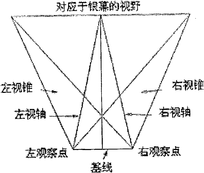
Due to traditional stereoscopic movies, the direction of parallax is fixed, such as figure 1 As shown, if strictly speaking theoretically, the stereoscopic effect of this fixed parallax is inaccurate. Except for the middle of the screen, the perspective relationship of the rest of the picture to the eyes is not accurate, and the stereoscopic effect of the scene cannot be accurately restored.
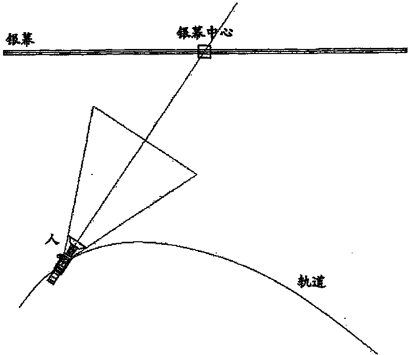
When in theme parks, digital stereo theaters, and other entertainment venues, because the audience is in motion, the relative positions of people and the screen may be in various states, and in most states, the baseline cannot be parallel to the screen, see figure 2 , the position and angle of view of the audience are constantly moving and changing, and the position and projection direction of the theater projector cannot be consistent with the audience. Only a row of images in the middle of the movie screen can have accurate perspective and parallax; where For images that are not in the center, their perspective and parallax have different degrees of deviation. The degree of deviation increases with the distance from the center of the screen, and the three-dimensional effect of the audience is very poor.

Method used


Image

  • Tracking visual field and method for making three-dimensional film by secondary rendering
  • Tracking visual field and method for making three-dimensional film by secondary rendering
  • Tracking visual field and method for making three-dimensional film by secondary rendering

Examples


Embodiment Construction

[0032] For the convenience of description, the spherical field of view stereo camera is now simplified as a single camera, and the following simple scene example is used to illustrate:

[0033] Such as Figure 6 Shown is a top view of the scene, Figure 7 is the perspective view of the scene. Among them, the teapot is "object A", the cube is "object B"; the bottom is "screen", "orbit" is an arbitrary curve parallel to the ground, the camera representing "person" moves along the orbit, and the target always points to the "screen center point" , "Projector" represents the on-site projector that finally projects the picture onto the screen in the theater.

[0034] Step 1: Record the scene information viewed from the perspective of the audience. For this purpose, place a camera at the position of the "person" and record the images observed in the field of view of the movement of the person. See Figure 8 .

[0035] Step 2: Since the final theater needs to project the image of ...


PUM


Abstract

The invention discloses a method for tracing view field and manufacturing stereoscopic film by twice rendering. The method comprises the following steps: (1) using a spherical view field stereoscopiccamera to trace and shoot image information observed by view field of human eyes, and rendering the shot image information through a computer; (2) using a digital projection device having the same optical characteristics as the camera to project an image to an actual projected screen position by same motion mode; (3) according to the principle of reversibility of an optical path, using a computerdigital camera which has same optical characteristics as a field projector to record the image mapped on the actual screen position; and (4) in a real playhouse, projecting the image finally renderedin step (3) onto the field screen through the field projector by a screening device, and making audiences in the same motion mode when the spherical view field stereoscopic camera shoots, so that theeffect of the image on the screen watched by the audiences in motion is same as the effect of the image watched by the audiences in real scene.

Description

technical field [0001] The invention belongs to the technical field of stereoscopic digital movies, and relates to a method for making stereoscopic movies. Background technique [0002] Stereoscopic movies are based on the basis of stereoscopic imaging, because people's two eyes are 6-7 cm apart, and when the left and right eyes look at objects, they see two slightly different images from different angles. After the parallax images are synthesized, the exact depth is judged to form a three-dimensional feeling. The traditional three-dimensional film is to use two cameras on the left and one right to shoot the same scene at the same time. During the projection, two projectors are used, each with a polarizer, and the images of the two polarized lights are projected on the screen at the same time. The vibration of the two polarized lights The directions are at right angles to each other. The audience wears special polarizers when watching stereoscopic movies. The vibration dire...

Claims


Application Information

Patent Timeline
Patent Type & Authority Patents(China)
IPC IPC(8): G03B35/00G03B35/08G03B35/18G06T15/70G06T13/20
Inventor 李明戎志刚丁亮崔涛霍彩霞
Owner FANTAWILD DIGITAL FILM
Learn More