Induction heating cooking device

A technology of induction heating and induction heating coils, which is applied in the direction of induction heating and induction heating devices, and can solve problems such as complicated structures

Inactive Publication Date: 2009-05-20
IRIS OHYAMA
View PDF1 Cites 5 Cited by
  • Summary
  • Abstract
  • Description
  • Claims
  • Application Information

AI Technical Summary

Problems solved by technology

For this reason, there is also a problem that a heat insulating structure must be provided bet

Method used


Image

  • Induction heating cooking device
  • Induction heating cooking device
  • Induction heating cooking device

Examples


Embodiment 1

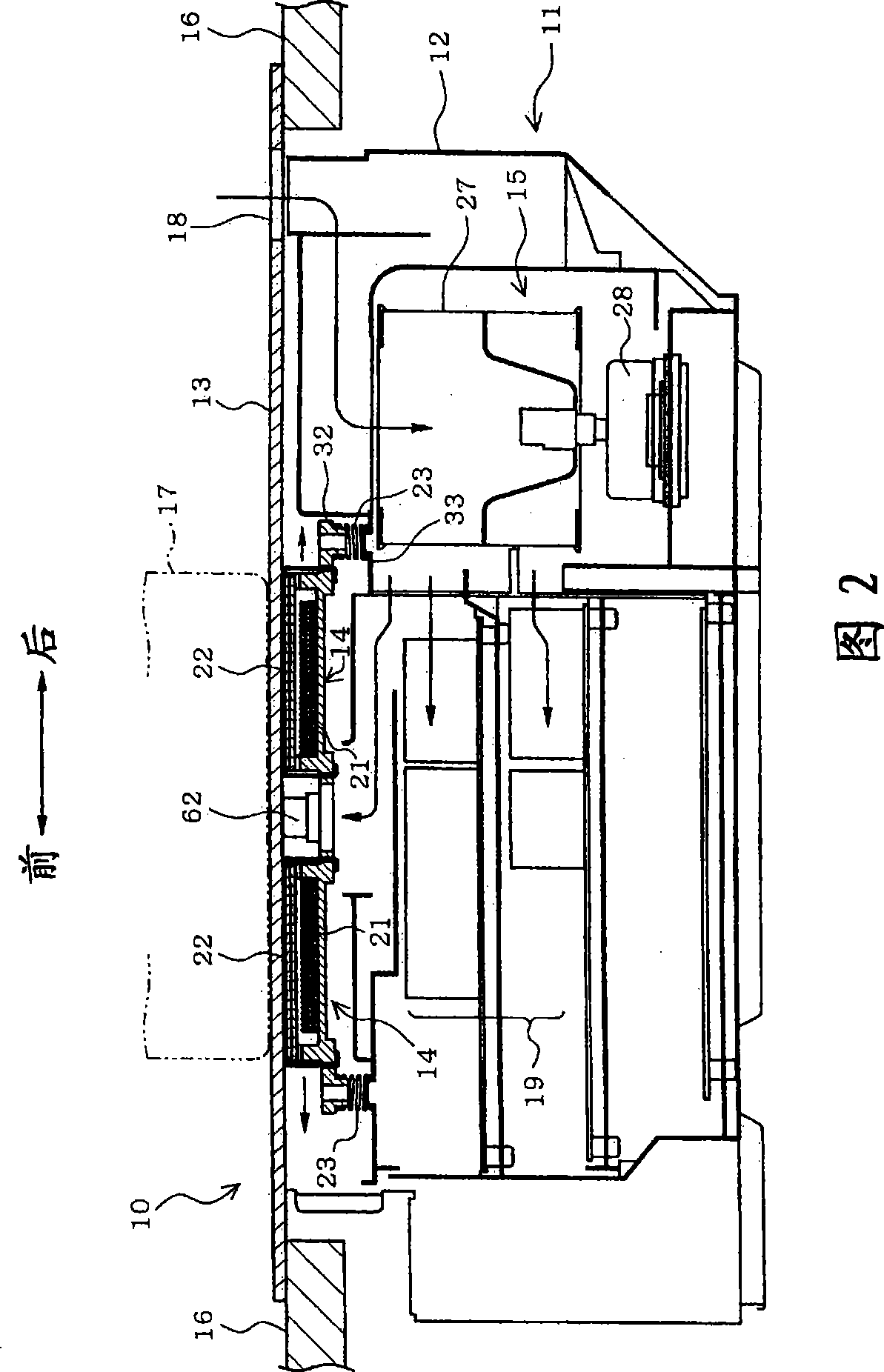
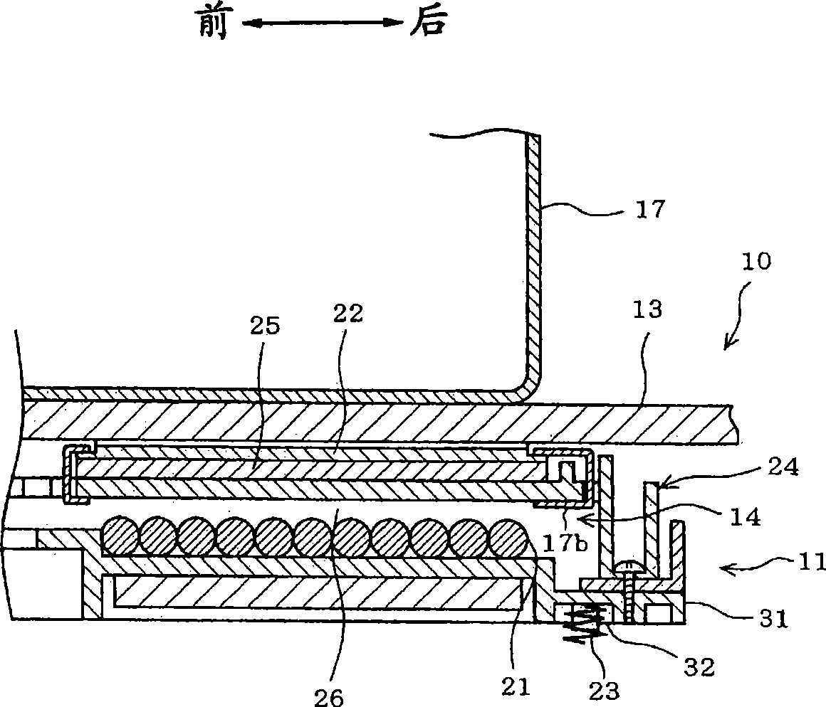
[0030] Fig. 2 shows an induction heating cooker according to Embodiment 1 of the present invention. The induction heating cooker 10 includes a main body case 12 and a top plate 13 constituting a cooker main body 11 . The induction heating cooker 10 is installed so that the top plate 13 is upward in the direction of gravity. In addition, in FIG. 2 , the left side is the front side of the induction heating cooker 10 , and the right side is the rear side of the induction heating cooker 10 . The induction heating cooker 10 includes a heating unit 14 and a cooling fan unit 15 in a cooker body 11 .

[0031]The main body casing 2 forms the main outer shape of the induction heating cooker 10 . The top plate 13 covers the top of the main body casing 12 . The cooker main body 11 is assembled to, for example, a countertop 16 of a kitchen unit. By means of this, the cooker main body 11 and its top plate 13 will be exposed from the work surface 16 . On the upper surface of the top pla...

Embodiment 2

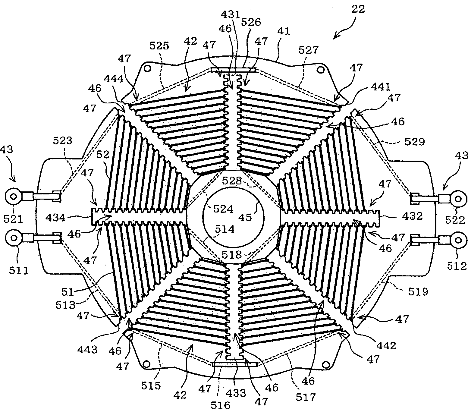
[0072] Figure 7 The plate-shaped heating body of the induction heating cooker of Example 2 of this invention is shown.

[0073] In Example 2, such as Figure 7 As shown, the plate heating body 122 has an insulating substrate 141 and a strip heater 142 . Figure 7 It is a schematic diagram of the plate-shaped heating body 122 viewed from the top plate 13 side, that is, a schematic diagram of the upper surface side. In the case of Example 2, the insulating substrate 141 is formed in an annular shape. The insulating substrate 141 has concavo-convex portions 146 on the inner peripheral side and the outer peripheral side in the diameter direction, respectively. The uneven portion 146 is formed with unevenness in the diameter direction of the insulating substrate 141 . The tape heater 142 is wound around the insulating substrate 141 while being folded back at the concave-convex portion 146 on the inner peripheral side and the concave-convex portion 146 on the outer peripheral s...

Embodiment 3

[0082] Next, Fig. 2 also shows a schematic configuration of an induction heating cooker according to Embodiment 3 of the present invention. The induction heating cooker 10 includes a main body casing 12 and a top plate 13 constituting a cooker main body 11 .

[0083] The induction heating cooker 10 is installed so that the top plate 13 is upward in the direction of gravity. In addition, in FIG. 2 , the left side is the front side of the induction heating cooker 10 , and the right side is the rear side of the induction heating cooker 10 . The induction heating cooker 10 includes a heating unit 14 and a cooling fan unit 15 in a cooker body 11 .

[0084] The main body casing 12 forms the main outline of the induction heating cooker 10 . The top plate 13 covers the top of the main body casing 12 . Cooker main body 11 is assembled, for example, to countertop 16 of a kitchen unit. With this, the cooker main body 11 and its top plate 13 will be exposed on the work surface. On th...


PUM


Abstract

The invention provides an induction heating cooking device. A strip heater (42) of a tabular heating body (22) emits heat owing to being electrified. The heating-cooking apparatus arranged at a roof (13), such as a pot (17) etc., can be heated directly by the tabular heating body (22). The major part of the heater (42) winded to the insulated substrate does not contact with the substrate (41) except a winding part of the heater (47). Therefore, the heat generated by the electricity does not make interaction between the substrate (41) of different thermal expansion coefficient and the heater (42) even if the heat takes the dimensional change in the heater (42). That is to say, the stress generated in the substrate (41) reduces even if the size of the heater (42) changes owing to the heat. As a result, the damage in the substrate (41), such as crack etc., does not generate owing to the heating of the heater (42) even if the difference of the coefficient between the substrate (41) and the heater (42) is big.

Description

technical field [0001] The present invention relates to an induction heating cooker, and more particularly to an induction heating cooker including a plate-shaped heating body between a top plate and an induction heating coil. Background technique [0002] In an induction heating cooker, when a cooking utensil to be heated formed of a material such as aluminum or copper with a low dielectric constant and high electrical conductivity is used, it often occurs that the cooking utensil to be heated is pushed against the top plate. The so-called "pot float" phenomenon of repulsion movement. Therefore, in order to heat the cooking utensil to be heated which is formed of a material with a low dielectric constant and a high electrical conductivity, it has been proposed to arrange a heating element between the top plate and the induction heating coil. However, in this case, the cooking utensil to be heated is also heated via the heat generating body heated by the induction heating c...

Claims


Application Information

Patent Timeline
IPC IPC(8): H05B6/12
Inventor 林秀竹江碕猛
Owner IRIS OHYAMA
Why Eureka
Try Eureka