Self-locking valve with valve cap

A self-closing, bonnet technology, applied in the direction of closing, safety valves, balance valves, etc., can solve problems such as large reset force, achieve the effects of simplifying the structure, saving materials, and improving air back-suction

Inactive Publication Date: 2009-05-20
HUSKY KTW
View PDF5 Cites 1 Cited by
  • Summary
  • Abstract
  • Description
  • Claims
  • Application Information

AI Technical Summary

Problems solved by technology

But such a deformation presupposes a large low pressure, so that the wall of the container must exert a correspondingly large restoring force

Method used


Image

  • Self-locking valve with valve cap
  • Self-locking valve with valve cap
  • Self-locking valve with valve cap

Examples


Embodiment Construction

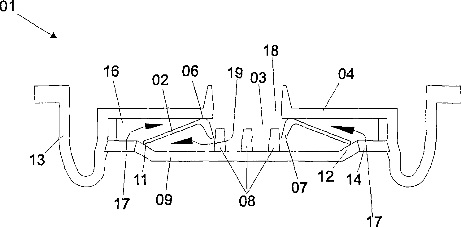
[0024] figure 1 A cross-sectional view of a first embodiment of the self-closing valve 01 according to the invention is shown in the closed position. Generally speaking, for the understanding of the figures, the valve 01 is designed to fit on a container (not shown), for example by fitting into the neck of a squeeze bottle.

[0025] The valve 01 comprises an annular valve membrane 02 having an annular central guide opening 03 . The valve membrane 02 is substantially in the form of a disk spring and also exhibits a relative spring characteristic. exist figure 1 The position of the valve membrane 02 when the valve 01 is closed is shown in . In this closed position, the valve membrane 02 is pressed with its periphery of the guide opening 03 onto the valve cover 04 . The circular bearing surface 06 thus formed seals the valve membrane 02 against the valve cover 04 . On the side of the valve membrane 02 opposite the bearing surface 06 , the guide opening 03 has a surrounding r...


PUM


Abstract

The invention relates to a self-locking valve (01) for releasing a product capable of flowing out of a volume. The valve comprises a valve cap (04) with an outlet (18); a guide disk (09) which is located on the product side of the valve cap and is at a distance to the valve cap; a valve membrane (02) which is supported between the valve cap (04) and the guide disk (09) and has a guide opening (03); a cavity (16) between the valve cap (04) and the valve membrane (02); at least one passage opening (14) which extends from the volume of the product to the cavity (16); a duct for sucking air back which is formed by means of the outlet (18), the guide opening (03), as well as by the opened air gap (23) resulting from lifting the valve membrane (02) off the guide disk (09).

Description

technical field [0001] The invention relates to a self-closing valve with a valve cover for the discharge of a flowable product. Background technique [0002] A typical application for a self-closing valve is a container in which the flowable content can be discharged by squeezing the container. So-called squeeze bottles for body care preparations are an example for this. Reducing the internal volume of the squeeze bottle by the user will increase the pressure within the squeeze bottle so that the contained product (eg liquid soap) will be delivered through the valve. Even when the container is no longer closed by means of a closure and the product acts on the outlet area of ​​the valve by its own weight, the self-closing action of the valve prevents the contents from being undesirably discharged without a pressure increase . [0003] DE 102 18 363 A1 discloses a self-closing valve for dispensing liquid or pasty products. The valve comprises a valve membrane which is con...

Claims


Application Information

Patent Timeline
Patent Type & Authority Applications(China)
IPC IPC(8): B65D47/20F16K17/04
CPCF16K17/19F16K15/144B65D47/2081
Inventor 乌多·祖法埃伯哈德·克布克
Owner HUSKY KTW
Why Eureka
Try Eureka