Valve cap for a non-return valve

A check valve, valve body technology, applied in the direction of transmission, belt/chain/gear, mechanical equipment, etc., to achieve the effect of improving hysteresis characteristics and optimizing switching characteristics

Inactive Publication Date: 2011-07-27
SCHAEFFLER TECH AG & CO KG
View PDF5 Cites 5 Cited by
  • Summary
  • Abstract
  • Description
  • Claims
  • Application Information

AI Technical Summary

Problems solved by technology

This known construction results in hydraulic adhesion of the valve body configured as a ball on the valve seat of the non-return valve

Method used


Image

  • Valve cap for a non-return valve
  • Valve cap for a non-return valve
  • Valve cap for a non-return valve

Examples


Embodiment Construction

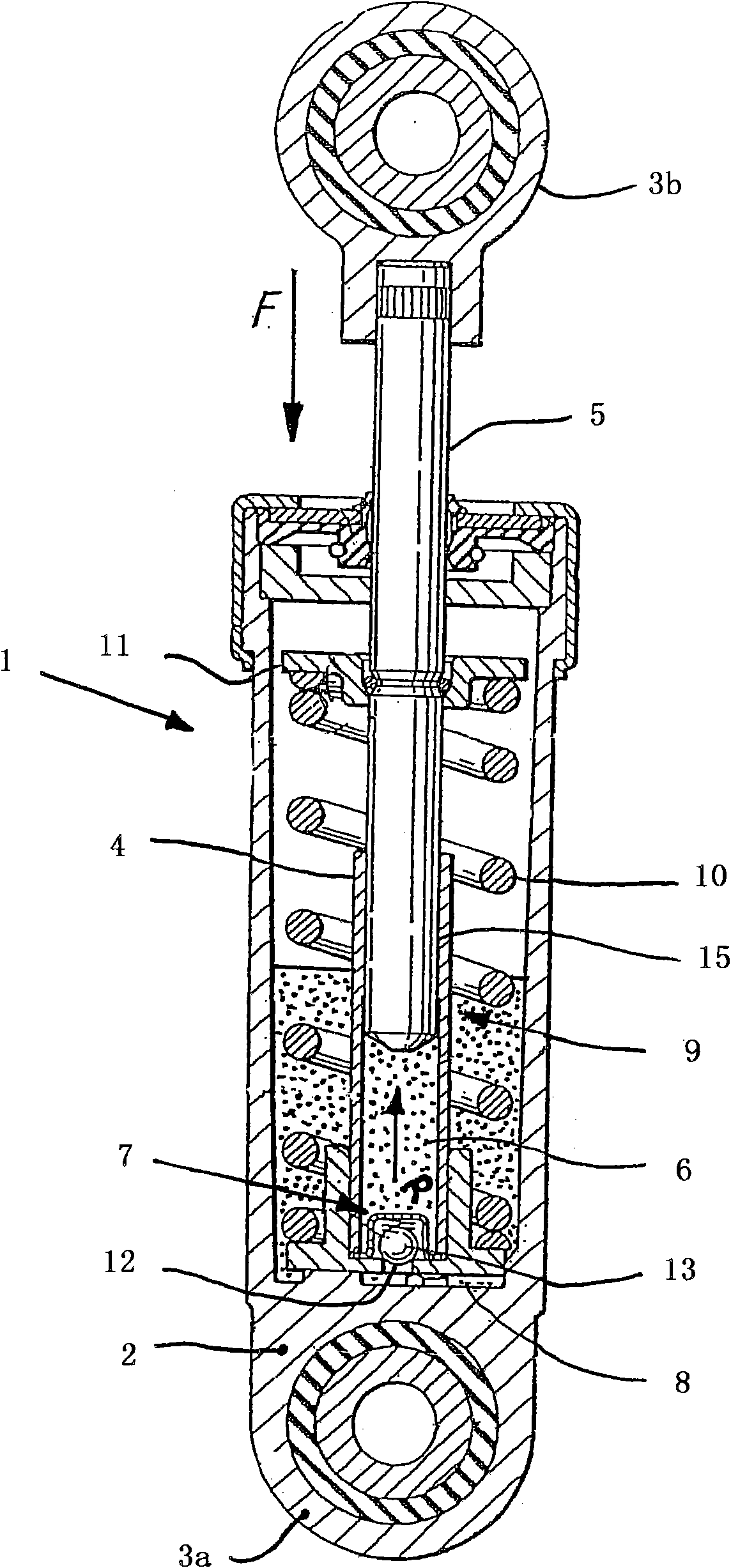
[0028] exist figure 1 The hydraulic tensioning system 1 is shown in cutaway diagram, the hydraulic tensioning system 1 is assigned to the traction mechanism transmission, and through figure 1 The tensioning roller, not shown in , directly interacts with the traction mechanism of the traction mechanism drive. The structure comprises a housing 2 , which is fixedly and pivotably connected, for example, to the housing of the internal combustion engine via fastening eyelets 3 a. The housing 2 forms a component having a pot-like configuration, in which a cylinder 4 is mounted centrally, which is defined to accommodate a linearly displaceable piston 5 . The cylinder 4 associated with the piston 5 delimits a pressure chamber 6 filled with hydraulic fluid, which is connected via a channel 8 of the housing 2 and a flow section 12 of the cylinder 4 to a reservoir 9 for hydraulic fluid. The reservoir 9 is delimited on the outside by the housing 2 and on the inside by the shell surface o...


PUM


Abstract

The present invention relates to a non-return valve (16) for a hydraulic tensioning system which is used in traction mechanism drives of internal combustion engines and which manipulates a hydraulic fluid flow between a pressure chamber (6) and a reservoir (9). The non-return valve (16) comprises a valve body (20) which is inserted in a housing (17) and which is embodied as a ball and which, when the non-return valve (16) is closed, is supported in a spring-loaded fashion against a valve seat (14) of a throughflow cross section (12). When the non-return valve (16) is open, the valve body (20) is assigned to a valve seat (21) of the housing (17), wherein the flow cross section (19) of the valve seat (21) ensures a fluid flow through the non-return valve (16).

Description

technical field [0001] The invention relates to a check valve used in a hydraulic tensioning system of a traction mechanism transmission device of an internal combustion engine. In the operating state, during the expansion phase of the tensioning system, the non-return valve can allow hydraulic fluid to flow from the hydraulic fluid reservoir into the high-pressure chamber. During the compression phase, the task of the non-return valve is to limit or inhibit the flow of hydraulic fluid. The structure of the non-return valve includes a housing, which is also described as a valve housing or holding means, into which is inserted, in particular, a valve body designed as a ball, which is held in a spring-loaded manner with the flow cross section. Background technique [0002] DE 40 35 823 C1 discloses a hydraulic tensioning system for a traction mechanism drive, in particular for a chain drive of an internal combustion engine. The tensioning piston, which pushes against the tra...

Claims


Application Information

Patent Timeline
Patent Type & Authority Applications(China)
IPC IPC(8): F16H7/08
CPCF16H2007/0859F16H7/0836F16H7/0848F16H2007/0806
Inventor 克里斯蒂安·沙费尔托马斯·克拉夫特伯恩特·哈特曼
Owner SCHAEFFLER TECH AG & CO KG
Why Eureka
Try Eureka