

Switched reluctance motor
a technology of switched reluctance and motor, which is applied in the direction of synchronous motors, mechanical energy handling, dynamo-electric components, etc., can solve the problems of low manufacturing cost, unbalanced attraction force, rotational vibration of motors, etc., and achieves the effect of increasing magnetic flux density, reducing manufacturing cost, and increasing the characteristics of switched reluctance motors
- Summary
- Abstract
- Description
- Claims
- Application Information
AI Technical Summary
Benefits of technology
Problems solved by technology
Method used
Image

Examples
first embodiment
[0051]A description will be given of a switched reluctance motor 100 according to a first embodiment of the present invention.
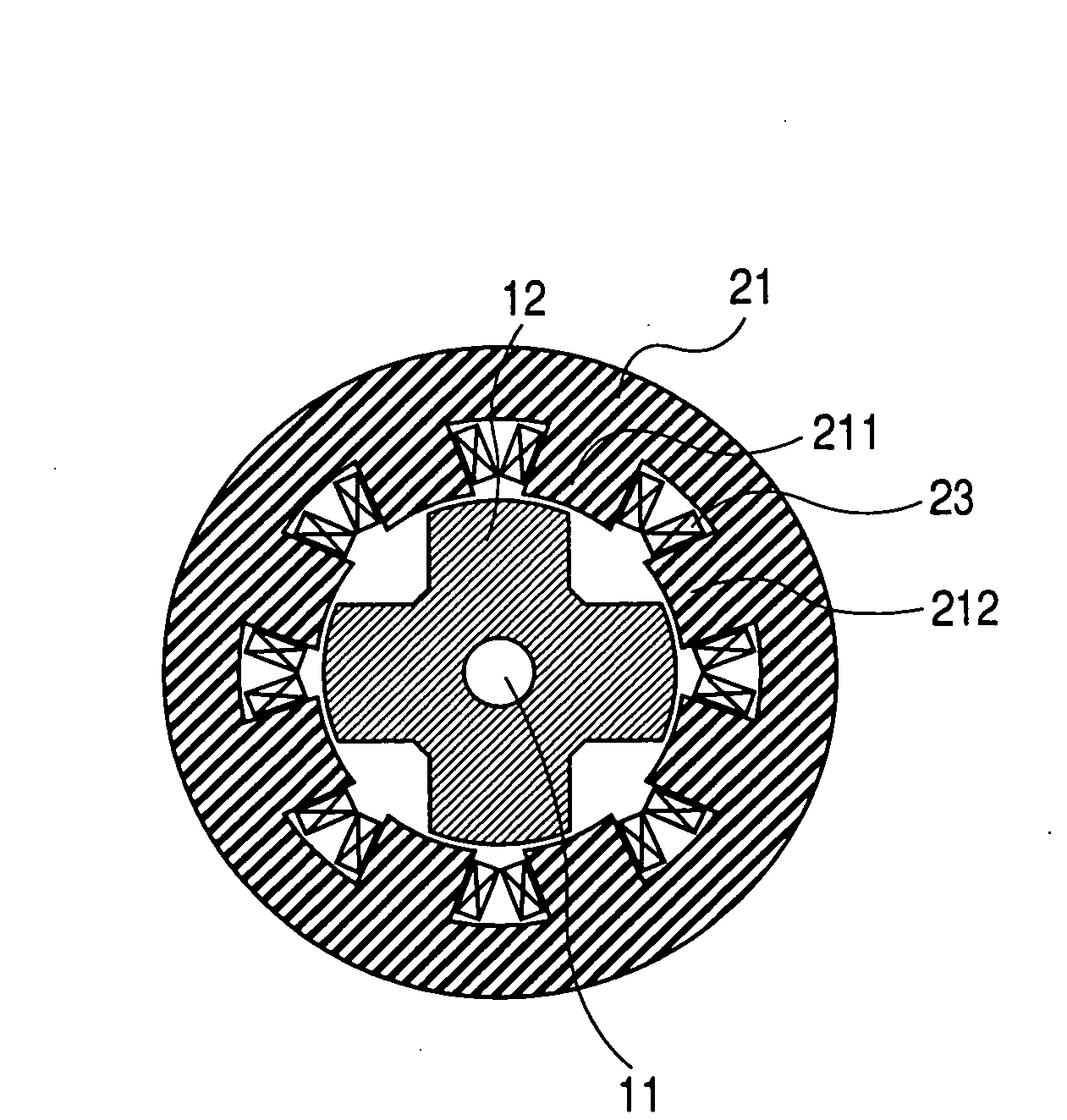
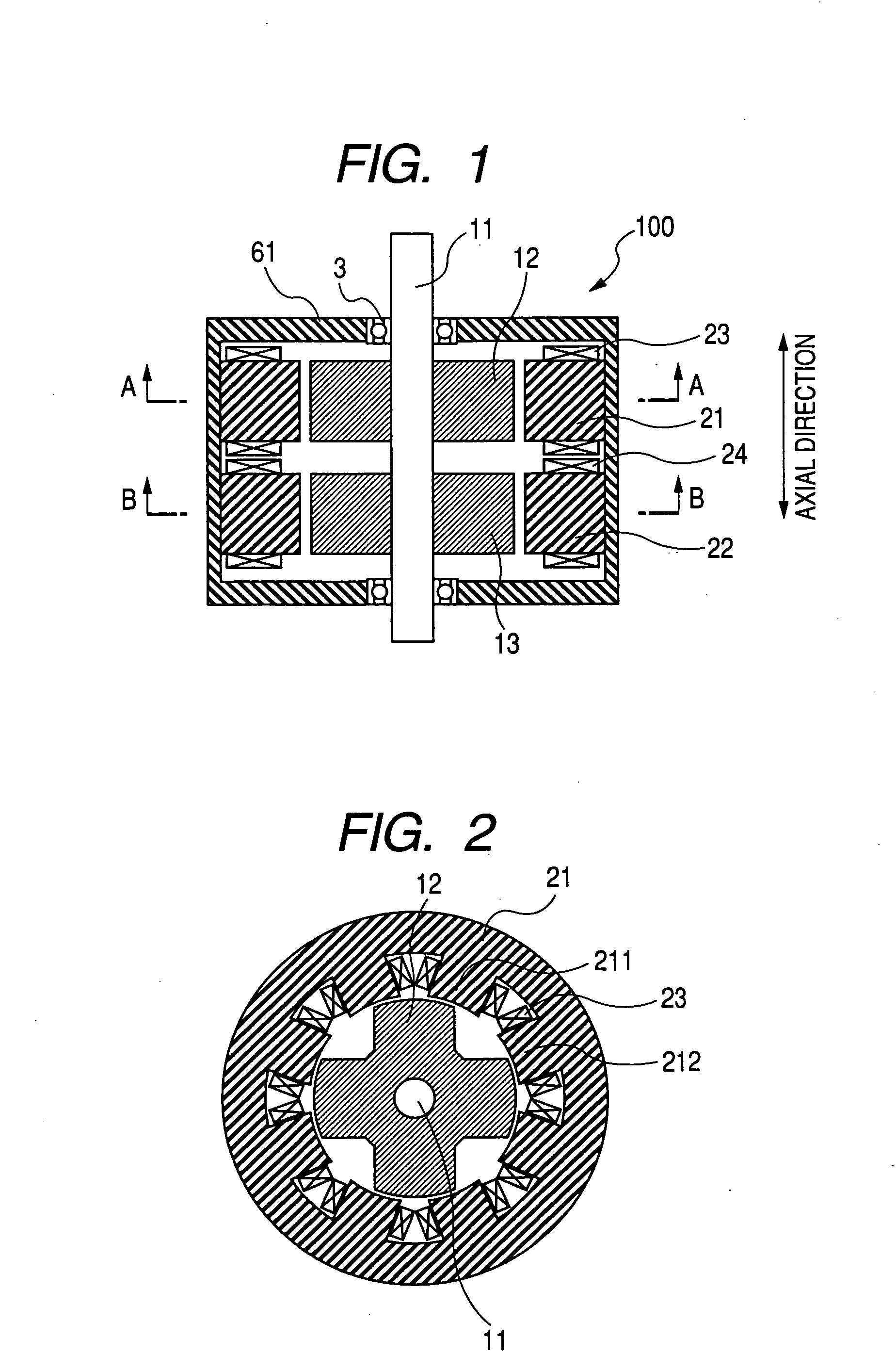
[0052]FIG. 1 is a schematic cross section of the switched reluctance motor 100 in its axial direction according to the first embodiment.
[0053]The switched reluctance motor 100 has the rotors 12 and 13. The rotors 12 and 13 are fitted and fixed to the rotary shaft 11 while being apart from each other at a predetermined distance in the axial direction of the switched reluctance motor 100.
[0054]The rotary shaft 11 is rotatably supported to the housing 61 through bearings 3.
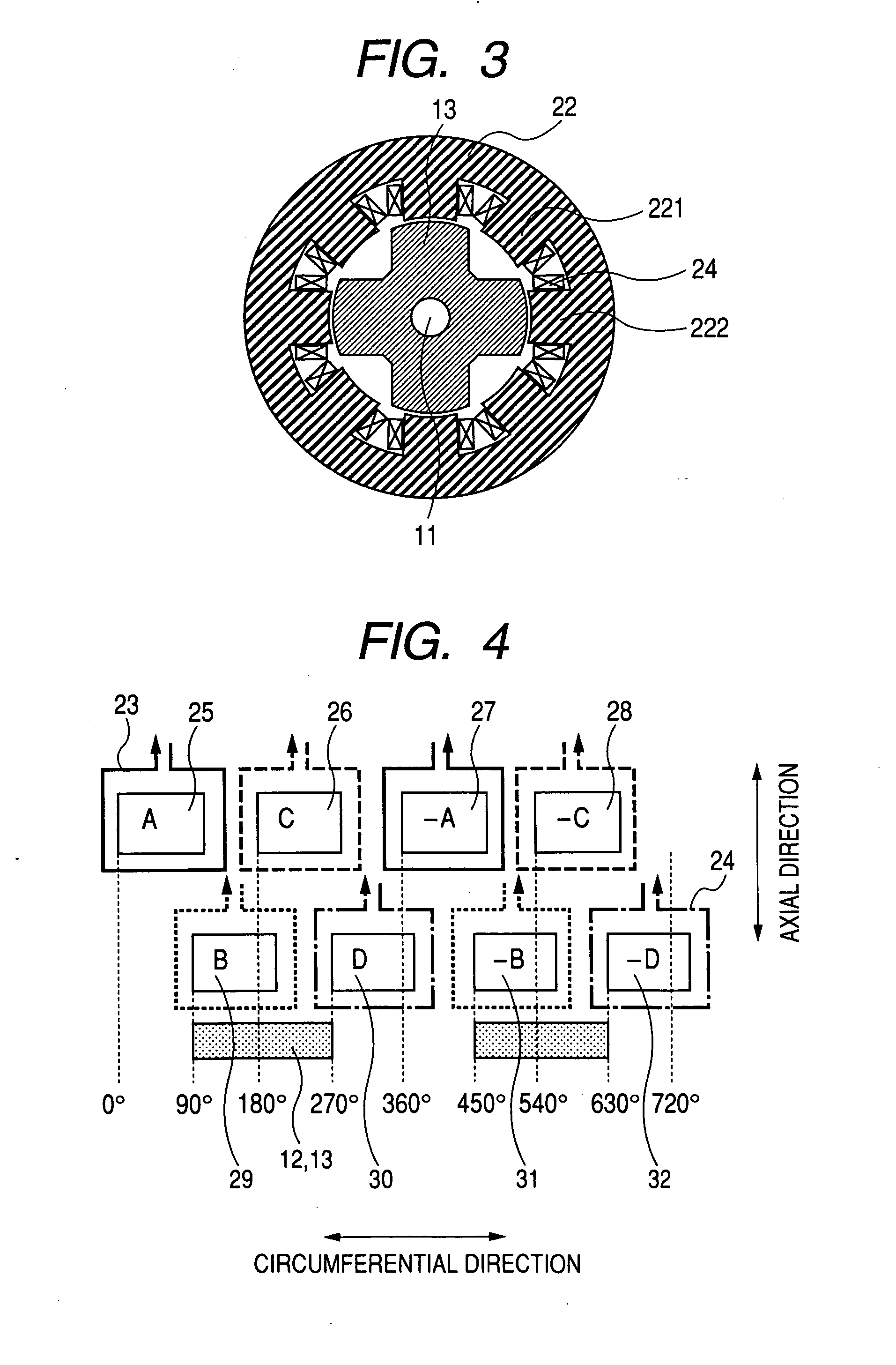
[0055]The stators 21 and 22 correspond to the rotors 12 and 13, respectively. Each stator has the cylindrical stator core and the stator coil 23.
[0056]In the stator 21, the cylindrical stator core is made of magnetic steel sheets which are laminated. The stator coil 23 is wound on the stator core. Similar to the stator core 21, the cylindrical stator core in the stator 22 is made of magnetic s...
second embodiment
[0095]A description will now be given of the switched reluctance motor 400 according to the second embodiment of the present invention with reference to FIG. 8 to FIG. 12.
[0096]The switched reluctance motor 400 according to the second embodiment basically has the same configuration of the switched reluctance motor according to the first embodiment shown in FIG. 1 to FIG. 4. The feature of the second embodiment which is different from that of the first embodiment will be mainly described.
[0097]FIG. 8 is a schematic cross section of the switched reluctance motor 400 in its axial direction according to the second embodiment. FIG. 9 is a schematic cross section of the switched reluctance motor 400 in its radial direction taken along an alternate long and short dash line E-E of FIG. 8. FIG. 10 is a schematic cross section of the switched reluctance motor 400 in its radial direction taken along alternate long and short dash line F-F of FIG. 8. FIG. 11 is a schematic cross section of the s...
third embodiment
[0109]A description will now be given of the switched reluctance motor 700 according to the third embodiment of the present invention with reference to FIG. 15 to FIG. 21.
[0110]The switched reluctance motor 700 according to the third embodiment basically has the same configuration of the switched reluctance motor according to the first and second embodiments. The feature of the third embodiment which is different from those of the first and second embodiments will be mainly described.
[0111]FIG. 15 is a schematic cross section of the switched reluctance motor 700 in its axial direction according to the third embodiment. FIG. 16 is a schematic cross section of the switched reluctance motor 700 in its radial direction taken along alternate long and short dash line H-H of FIG. 15. FIG. 17 is a schematic cross section of the switched reluctance motor 700 in its radial direction taken along alternate long and short dash line I-I of FIG. 18. FIG. 18 is a schematic cross section of the swit...
PUM
 Abstract
Description
Claims
Application Information