
Active support surface

Inactive Publication Date: 2010-10-21
KILBORN JOHN C
View PDF2 Cites 45 Cited by
  • Summary
  • Abstract
  • Description
  • Claims
  • Application Information

AI Technical Summary

Benefits of technology

[0080]The controller means can include one or more of the following means: means for sensing and relieving sustained compression of tissues occurring in occupants of the mattresses, overlays and / or seating; means for mimicking a response of a passive support surface to the externally applied forces; means for generating surface vibration so as to reduce a coefficient of friction of the support surface; means for sensing and reducing external vibrational forces communicated to the occupant; means for determining a location of the occupant on the support surface; means for identifying a probable posture of the occupant and recording changes in the probable posture within a patient electronic medical record; means for generating an alert in the event that the probable occupant posture does not change for a predetermined interval of time; means for facilitating user-directed massage; means for adopting support surface contours in response to changes in the occupant location and the probable occupant posture; means for controlling firmness and stability of the support surface; and means for synthesizing one or more responses by the support surface to the externally applied forces.
[0084]The active devices are caused at and proximal to the locations of the peak forces to retract their movable ends by variable amounts. This reduces resistive forces on occupant surface tissues at and proximal to locations of peak forces. Further, the method includes optionally causing the active devices distal to the locations of the peak forces to extend their movable ends by variable amounts. This increases the resistive forces on the occupant surface tissues at locations distal to the peak forces. Further, velocities of the movable ends are configured so as to limit impact forces on the occupant, until the locations of the peak forces change or a predetermined set time interval has elapsed. The time interval is capable of being set to ranges of seconds to minutes. The method further includes selectively updating the activation signals, so that the updated signals cause the active devices having movable ends in a retracted state to extend the movable ends by variable amounts, so as to increase the resistive forces on the occupant surface tissues at corresponding locations. Further, velocities of the movable ends are configured so as to limit the impact forces on the occupant, wherein the updated activation signals optionally cause the active devices having movable ends in an extended state to retract by variable amounts, so as to reduce the resistive forces on the occupant surface tissues at corresponding locations. Still further, the method includes effecting changes in magnitudes and directions of stress vectors in occupant deep tissues. This occurs through changes in the resistive forces on the occupant surface tissues and interrupting sustained compression of the deep tissues.
[0087]A further method in accordance with the invention includes adjusting the firmness and stability of the mattresses, overlays and / or seating. The method also includes selecting a desired level of firmness and stability, and decreasing amplitude of the direct impulse responses in response to an increase in firmness. Amplitude of the direct impulse responses is increased in response to a decrease in firmness. Decreasing the amplitude and / or length and / or oscillations of the indirect impulse responses in response to an increase in stability is also accomplished. In addition, the method includes increasing the amplitude and / or length and / or oscillations of the indirect impulse responses in response to a decrease in stability.
[0091]Methods in accordance with the invention also include generating surface vibration in mattresses, overlays and / or seating so as to reduce a coefficient of friction of a support surface, using an array of active devices having the stationary ends and movable ends. Activation signals are applied to the active devices to forcibly move the movable ends, the movement being generated by deformation of the polymer actuators. The movable ends are extended and retracted at frequencies of at least 10 Hz. For specific intervals of time, movable ends of one group of the active devices are retracted, and movable ends of a second group of the active devices are extended. An area of surface contact is reduced between an occupant and the mattresses, overlays and / or seating.
[0095]Certain ones of the active devices can be extended which are located in a thoracic back region of a supine occupant, so as to improve respiration of the occupant. Certain ones of the active devices can be extended which are located in a popliteal region of a supine occupant, so as to reduce lower back strain.
[0096]Certain ones of the active devices can also be extended, which are located forward of ischial tuberosites of a reclining occupant, so as to prevent sliding. Devices can also be extended which are located lateral to a thorax of a seated occupant, so as to provide lateral support.

Problems solved by technology

However, because of the nature of most gels, the accommodation of the gels to relatively high forces is somewhat limited.
They are sometimes perceived as noisy, uncomfortable and unreliable.
This is as a result of the mattresses' inherent lack of stability.
This lack of stability also complicates patient transfers and CPR administration, and hinders a patient's efforts to self-mobilize.
Furthermore, specialty mattresses are expensive, ranging from $800 to $6000 per system, depending on the feature set.
It has been well established that tissue damage is often apparent following prolonged loading, even at relatively low level pressure intensities.
However, because the cells that compose alternating pressure mattresses are large, the relief they provide to the deep tissues is imprecise.
Moreover, there is a risk, again due to cell size, that when one row of cells is deflated, localized pressures over an adjacent (inflated) row of cells will attain unsafe levels, as that portion of the body is asked to bear more of the patient's total body weight.
Considering that at-risk patients are supposed to be turned by staff at least every 2 hours, the degree of alignment is not assured.
Finally, and perhaps most importantly, the cycle times of alternating pressure mattresses are long (measured in minutes) and thus may significantly prolong tissue recovery times in high risk patients.
There is strong evidence that surface (interface) pressures are not representative of the internal mechanical conditions inside the tissue, which are most relevant for tissue breakdown, especially when tissue geometry and composition are complex and surface pressures result in highly inhomogeneous internal mechanical conditions.
Short term loading generally produces elastic recovery, while long term loading results in the creep phenomenon and requires a longer time for complete tissue recovery.
Most of these products use electromechanical actuators to generate the massaging motion, which limits the precision, speed, flexibility and dexterity of these motions, as well as the ability of the user to control them.
Also, because electromechanical actuators are bulky, the technology does not lend itself to broader application.
Further, an occupant's comfort preferences may evolve over time, so the likelihood that a particular type of mattress will satisfy its occupants for the duration of its warranty period (typically 10 years) is low.
However, the cell size in these mattresses is large and, consequently, the adjustments are gross in nature.
Existing mattresses are incapable of determining occupant positions and unable to adjust their contours.
A cursory examination of the technologies used in conventional specialty mattresses and overlays reveals their limitations as enabling technologies for these new concepts.
An implementation based on air- or fluid-filled cells would require hundreds of cells and valves, and a complex and expensive routing system (for air or fluid) to control cell movements independently.
Achieving the combined force and speed necessary for effective relief, given the size constraint imposed on individual cells, would be very difficult.
Also, aside from presenting a daunting manufacturing challenge, such an implementation would be noisy.
Electromagnetic actuators are generally large, heavy, expensive, noisy and power-hungry.
While they can generate considerable linear force, they do not provide the combination of speed and precision necessary for comfortable, effective relief.
An implementation based on pneumatic actuators would require hundreds of valves and a complex and expensive routing system (for the compressed air that drives these actuators) to control actuator movements independently.
Aside from being noisy, and similar to electromagnetic actuators, pneumatic actuators do not provide the combination of speed and precision necessary for comfortable, effective relief.
In addition, EAPs consume very little power, and enable the construction of relatively small devices.

Method used


Image

  • Active support surface
  • Active support surface
  • Active support surface

Examples


Embodiment Construction

[0118]The principles of the invention are disclosed, by way of example, with respect to active support assemblies as described herein and illustrated primarily in FIGS. 2-19. More specifically, active support assemblies in accordance with the invention are described in detail herein with reference to a plurality of preferred embodiments as illustrated in the drawings. Numerous specific details are set forth herein for purposes of providing a thorough understanding of the present invention. However, it should be apparent to one skilled in the art that the present invention may be practiced without some or all of the specific details. That is, well known process steps and / or structural elements have not been described in detail, so as to not unnecessarily obscure the present invention.

[0119]As will be made apparent from subsequent description herein, the invention in part is comprised of a system for enhancing comfort and / or postural support afforded occupants of mattresses, overlays,...


PUM


Abstract

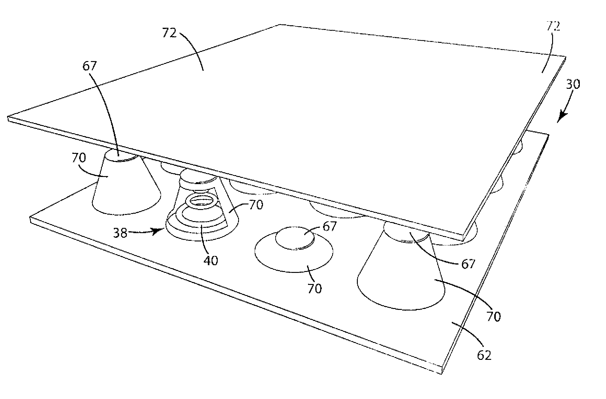
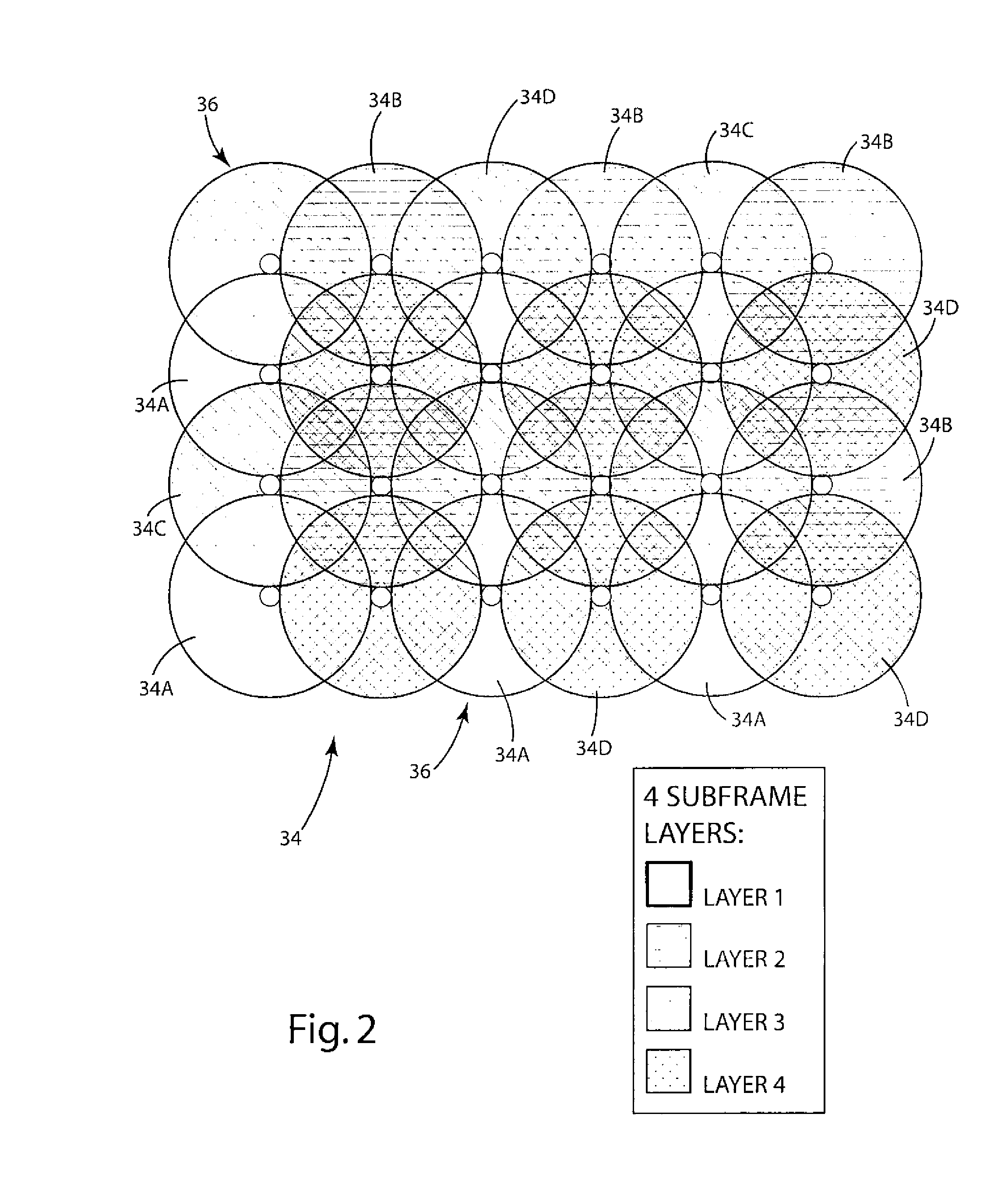
An active support assembly (30) includes a frame assembly (32) having subframes (34). Active devices (36) includes a flexible element (38) having a stationary end (40) attached to the frame assembly (42). An opposing end of each of the active devices (36) or flexible elements (38) also include a movable end (42). Electroactive polymer actuators (70) are organized into an array (68), with each actuator (70) aligned with a flexible element (38). Increases in the level of the activation signals cause the corresponding actuators (70) to expand, and forcibly extend the movable ends (42), with expansion of the flexible elements (38). The active support assemblies can be used with mattresses, overlays and seating for purposes of adjusting the same in response to the application of external forces caused by an occupant.

Description

CROSS-REFERENCE TO RELATED APPLICATIONS[0001]This application claims priority and is based upon U.S. Provisional Patent Application Ser. No. 61 / 161,195, filed Mar. 18, 2009.STATEMENT REGARDING FEDERALLY SPONSORED RESEARCH OR DEVELOPMENT[0002]Not applicable.REFERENCE TO MICROFICHE APPENDIX[0003]Not applicable.BACKGROUND OF THE INVENTION[0004]1. Field of the Invention[0005]The invention relates to support assemblies for facilitating comfortable support of human individuals and, more particularly, to active support assemblies having means for movement in response to application of external forces.[0006]2. Background Art[0007]Subjects who are seated or recumbent for long periods of time are exposed to sustained mechanical forces. These forces can comprise a compressional and, in some cases, a vibrational component. The impact of these compressional and vibrational component forces on both subject comfort and soft tissue viability can be significant. Specifically, depending upon: (a) the...

Claims


Application Information

Patent Timeline
IPC IPC(8): A61B5/103A61G7/065A61G7/05
CPCA61B5/103A61B5/412A61B5/6887A61G7/057A61H2201/5023A61G2203/32A61G2203/36A61H2201/0142A61H2201/5007A61G7/05707
Inventor KILBORN, JOHN C.
Owner KILBORN JOHN C
Learn More