Integrated temperature sensor

A temperature sensor and sensor technology, applied in thermometers, instruments, and thermometers based on the expansion/contraction of materials, etc., can solve problems such as large resistance bands

Inactive Publication Date: 2009-05-20
KONINKLIJKE PHILIPS ELECTRONICS NV
View PDF0 Cites 16 Cited by
  • Summary
  • Abstract
  • Description
  • Claims
  • Application Information

AI Technical Summary

Problems solved by technology

The disadvantage is that to achieve sufficient accuracy, the resistive bands are relatively large (micrometers in width and hundreds of micrometers in length) so tha...

Method used


Image

  • Integrated temperature sensor
  • Integrated temperature sensor
  • Integrated temperature sensor

Examples


Embodiment Construction

[0027] The present invention will be described with respect to particular embodiments and with reference to certain drawings but the invention is not limited thereto but only by the claims. Any reference signs in the claims should not be construed as limiting the scope. The drawings described are only schematic and not restrictive. In the drawings, the size of some of the elements is exaggerated and not drawn on scale for illustrative purposes. The term "comprising" is used herein in the description and claims, but it does not exclude other elements or steps. Where an indefinite or definite article is used herein when referring to a singular noun eg "a", "the", this includes a plural of that noun unless something different is specifically stated.

[0028] Also, the terms first, second, third, etc. in the description and claims are used to distinguish between similar elements and are not necessarily used to describe a sequence or chronological order. It is to be understood t...


PUM

PropertyMeasurementUnit
Lengthaaaaaaaaaa

Abstract

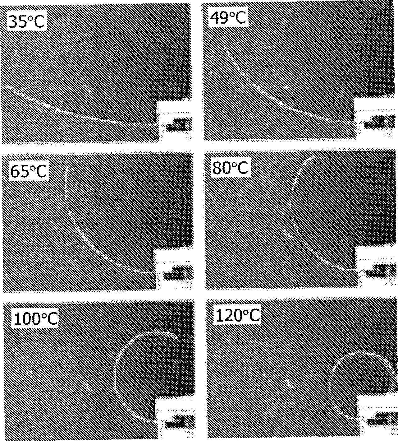
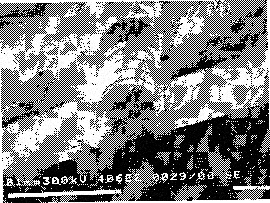
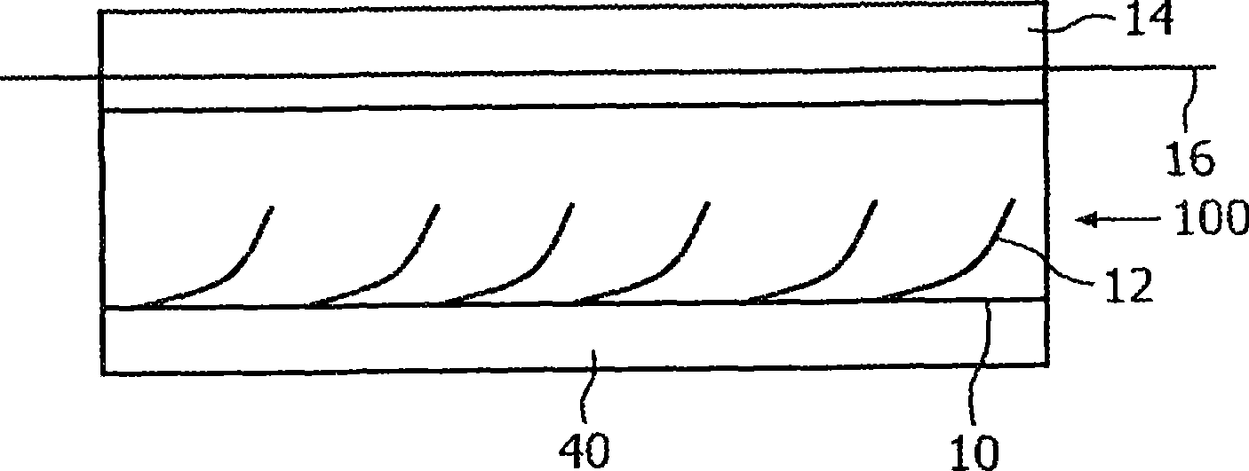
A biochip has an integrated temperature sensor comprising a micro mechanical actuator (20) having a deformation dependent on temperature, and a detector (30) arranged to output a signal according to a deformation of the actuator. The actuator (comprising a thermally actuable polymer) can be formed of LC Liquid Crystal material in an elastomeric network. The detector (30) can be optical, magnetic or capacitive. The actuator can be arranged as a layer and the deformation be a curling of the layer.

Description

technical field [0001] The present invention relates to integrated temperature sensing devices and corresponding methods, in particular "system-on-chip" or "experiment-on-a-chip" such as integration in MEMS devices, sensors, especially biosensors, molecular diagnostic devices, bioreactors and microfluidics. temperature sensing devices in chambers, etc. Background technique [0002] MEMS devices are known for many fields of application, including biosensors and biochips for (bio)chemical analysis, such as molecular diagnostics, in various medical, forensic and food applications. Typically, biochips include biosensors in which target molecules (eg proteins, DNA) are immobilized on biochemical surfaces with capture molecules and subsequently detected eg with optical, magnetic or electrical detection schemes. [0003] "Thermo-Mechanical Responses of Liquid-Crystal Networks with a Splayed Molecular Organization" by Grietje N. Mol, Kenneth D. Harris, Cees W.M. Bastiaansen and Dir...

Claims


Application Information

Patent Timeline
IPC IPC(8): G01K5/48
CPCG01K5/486
Inventor J·M·J·登东德A·博斯
Owner KONINKLIJKE PHILIPS ELECTRONICS NV
Why Eureka
Try Eureka