

Chucking appliance for self-positioning of finish surface and operation method thereof
A technology for processing surfaces and fixtures, applied in positioning devices, manufacturing tools, metal processing equipment, etc., can solve the problems of inability to obtain geometric tolerances and assembly accuracy, low efficiency, etc., and achieve convenient positioning, accurate position, and guaranteed position accuracy. Effect
- Summary
- Abstract
- Description
- Claims
- Application Information
AI Technical Summary
Problems solved by technology
Method used
Image

Examples
Embodiment 1
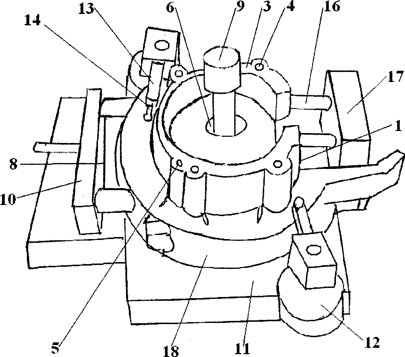
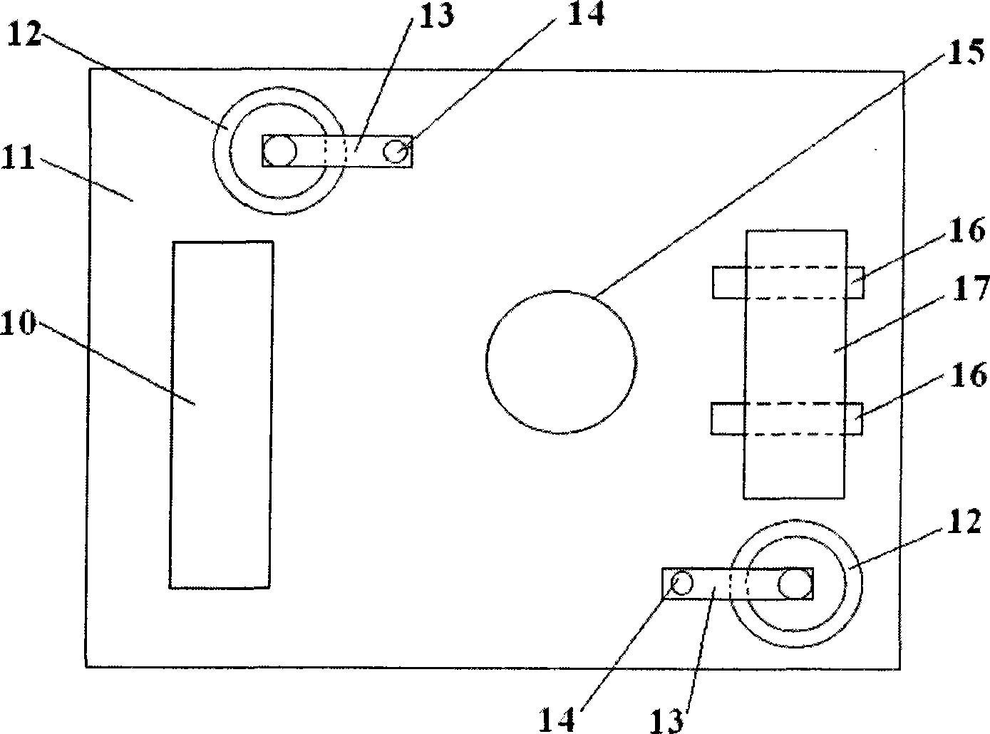
[0027] On the profile 2 of the workpiece 18 described in the present invention, the side rough positioning surface 1 is established; at the corresponding position on the described clamp, a rough positioning rod 16 is established to contact it, and the described coarse positioning rod 16 is formed by a positioning rod seat 17 Fixed, the positioning rod seat 17 is fixed on the clamp base 11.
[0028] Coarse positioning is completed through the initial cooperation of the fixed bolt 9 and the rough positioning rod 16 in the center. There are generally two coarse positioning rods 16 .
Embodiment 2
[0030] On the profile 2 of the workpiece 18 described in the present invention, a side fine positioning surface 8 is established; at the corresponding position on the described clamp, a pneumatic positioning plate 10 is established, and when performing fine positioning, the pneumatic positioning plate 10 and The side fine positioning surface 8 is in contact.
[0031] Then utilize the pneumatic device to carry out the tight surface contact between the side fine positioning surface 8 on the part and the pneumatic positioning plate 10; start the pneumatic clamping device to press figure 1 Clamp as shown; pull out the fixed pin 9 in the center to complete the positioning of the workpiece 18. With this method, the positioning is accurate and reliable, and the use is convenient and quick.
Embodiment 3
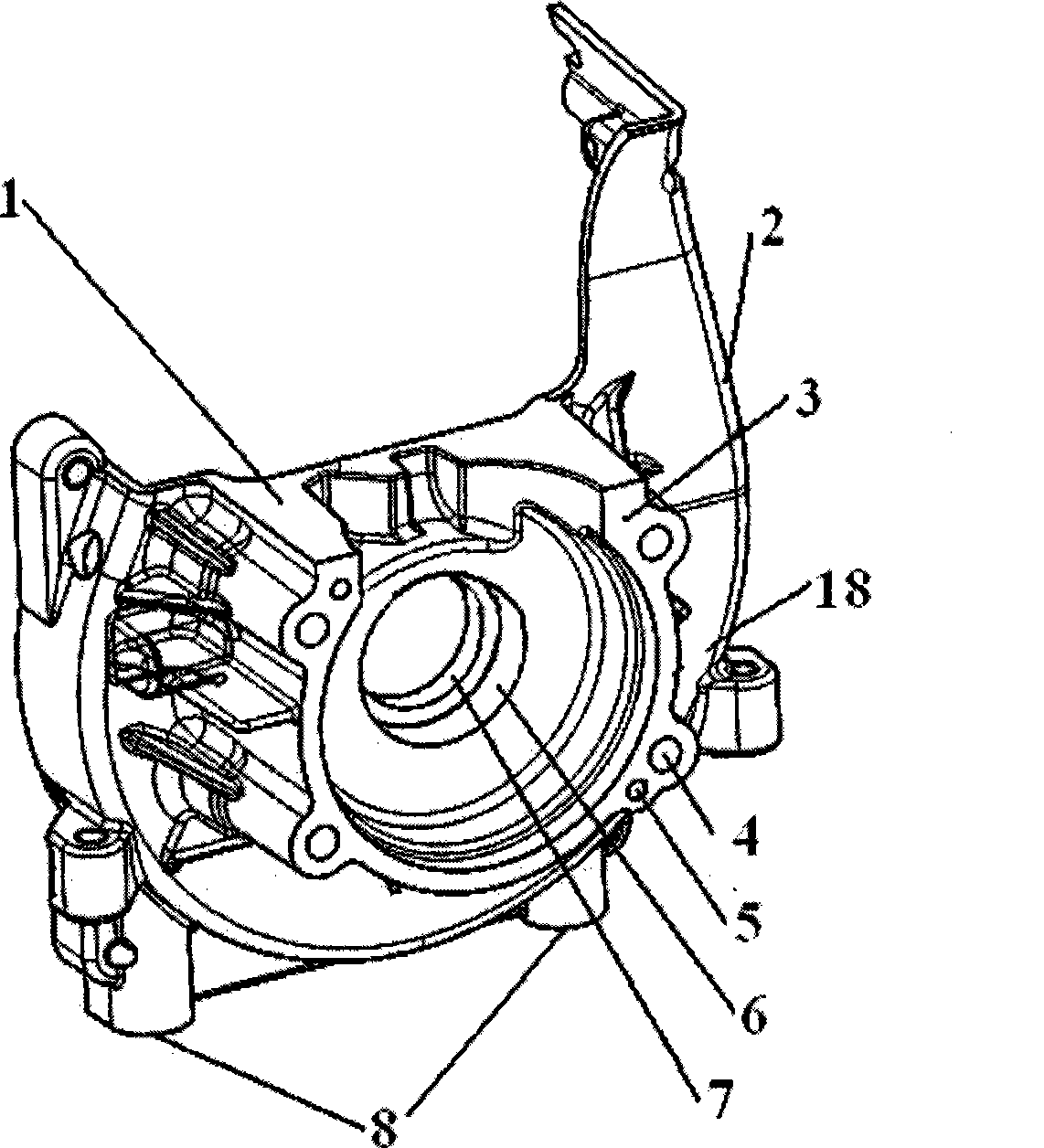
[0033] by figure 2 The shown workpiece 18 is an example, and its processing operation steps are as follows:
[0034] First install as figure 1 and image 3 The fixture shown; the side rough positioning surface 1 of the workpiece 18 is pressed figure 1 After the shown position leans on the coarse positioning rod 16, press the fixed bolt 9 with the center that has been processed. image 3 Shown method, insert in the central through hole 7 of workpiece to be processed; Subsequently, as figure 1 and image 3 As shown, start the cylinder behind the pneumatic positioning plate 10 to realize the fast clamping and pushing of the pneumatic positioning plate 10 to ensure that the side fine positioning surface 8 on the workpiece 18 is in contact with each other; start the clamping cylinder again, and use the pneumatic device to perform the following steps: figure 1 After the shown pneumatic clamping, the center pin 9 is pulled out to complete the final accurate positioning of the w...
PUM
 Abstract
Description
Claims
Application Information