

Ticket clip
A ticket clip and ear clip technology, applied in printing, binding and other directions, can solve the problem of inconvenient sorting and storage of bills, and achieve the effect of simple structure and convenient use.
Inactive Publication Date: 2009-05-27
NANTONG YIXUE STATIONERY
View PDF0 Cites 0 Cited by
- Summary
- Abstract
- Description
- Claims
- Application Information
AI Technical Summary
Problems solved by technology
[0003] In order to overcome the disadvantage that the existing single-layer bill holder is very inconvenient for sorting and storing bills, the present invention provides a bill holder, which is a multi-layer bill holder, so that it is very convenient for sorting and storing bills
Method used
View moreImage
Smart ImageViewing Examples

Examples
Embodiment Construction
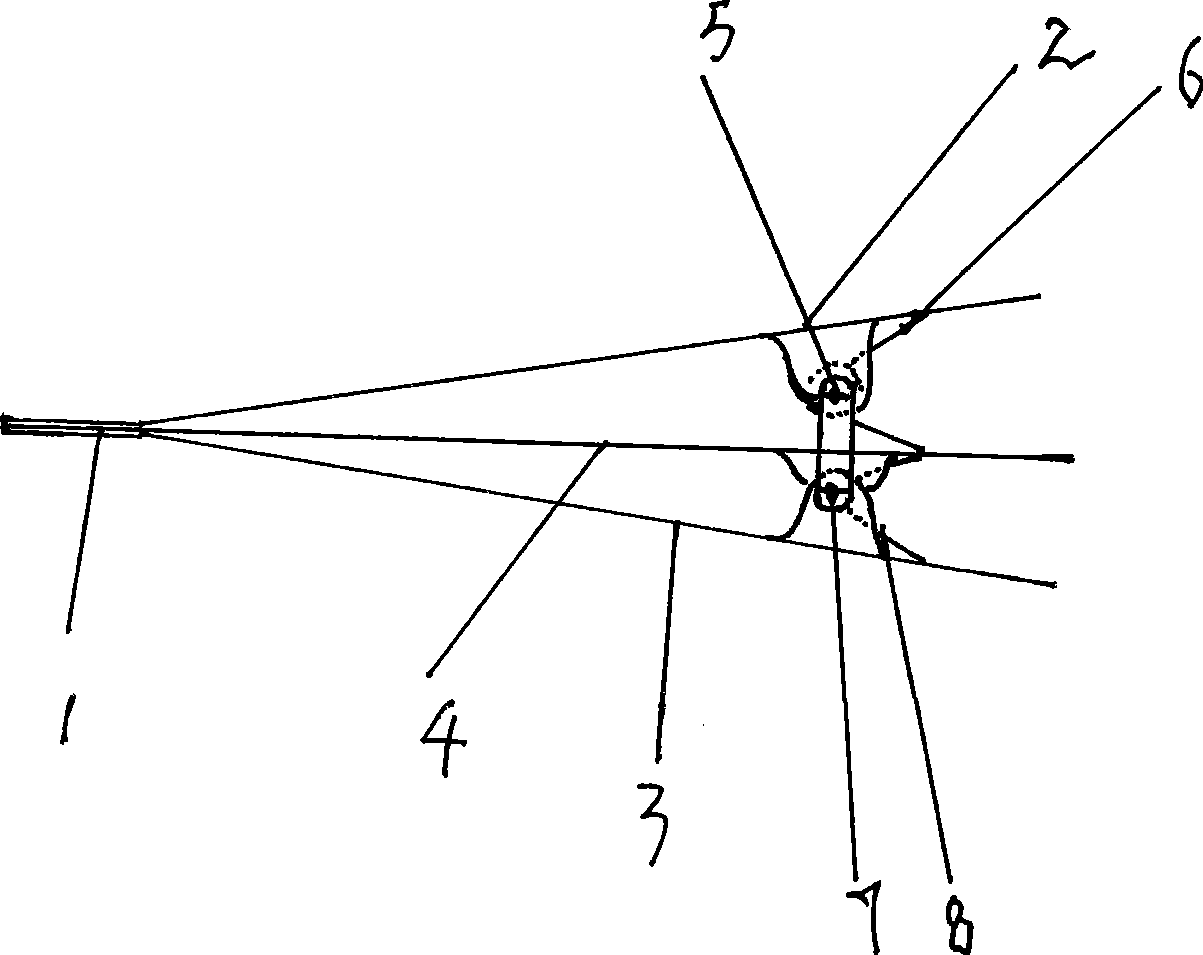
[0011] In the figure, the single-side ear clip a (2) and the single-side ear clip b (3) are on both sides of the ticket holder (1), the double-sided ear clip (4) is in the middle of the ticket holder (1), and the spring a (6) String in the small shaft a (5), the small shaft a (5) is stringed in the small holes on the small ears of the single ear clip (2) and the double ear clip (4), the spring b (8) The string is in the small shaft b (7), and the small shaft b (7) is stringed in the small holes on the small ears of the unilateral ear clip (3) and the bilateral ear clip (4).
Login to View More PUM
 Abstract
The invention relates to a bill fold containing multilayer folders for conveniently storing the bills in a bill arranging fold according to categories. The bill fold consists of a single-side ear clamping piece a, a single-side ear clamping piece b, a double-side ear clamping piece, a small shaft a, a spring a, a small shaft b, and a spring b. The bill fold is characterized in that the double-side ear clamping piece is arranged between the single-side ear clamping piece a and the single-side ear clamping piece b; the spring a is arranged in the small shaft a, and the small shaft a is inserted into small holes on small ears of the single-side ear clamping pieces and the double-side ear clamping piece; the spring b is arranged in the small shaft b, and the small shaft b is inserted into the small holes on the small ears of the single-side ear clamping pieces and the double-side ear clamping piece. The multilayer bill fold can achieve the purpose of sorting, arranging and storing the bills.
Description
Technical field [0001] The invention relates to a bill holder which includes multi-layer folders in a whole bill holder for convenient classification and storage of bills. Background technique [0002] At present, the kind of known ticket holder is a lot, and a kind of is to be provided with the ticket holder of spring in the axle center, and a kind of is the ticket holder of shrapnel type, but their interlayer is a single layer, very inconvenient when sorting and keeping bills, Generally, the bills are clipped together for storage, and all bills must be removed or clipped when using the bills. Contents of the invention [0003] In order to overcome the disadvantage that the existing single-layer bill holder is very inconvenient for sorting and storing bills, the present invention provides a bill holder, which is a multi-layer bill holder, so that it is very convenient for sorting and storing bills. [0004] The technical solution adopted by the present invention to solve...
Claims
Login to View More Application Information
Patent Timeline
 IPC IPC(8): B42F1/02
Inventor朱志明
OwnerNANTONG YIXUE STATIONERY