

Device for melt spinning of a linear filament bundle
A technology of melt spinning and monofilament, which is applied in the direction of melt spinning, textile and papermaking, and spinneret assembly, etc., which can solve the difference in the melt of the filament group and cannot ensure the production of uniform monofilament clusters, and the physics of the filament group Different characteristics and other problems, to achieve the effect of uniform distribution
- Summary
- Abstract
- Description
- Claims
- Application Information
AI Technical Summary
Problems solved by technology
Method used
Image

Examples
Embodiment Construction
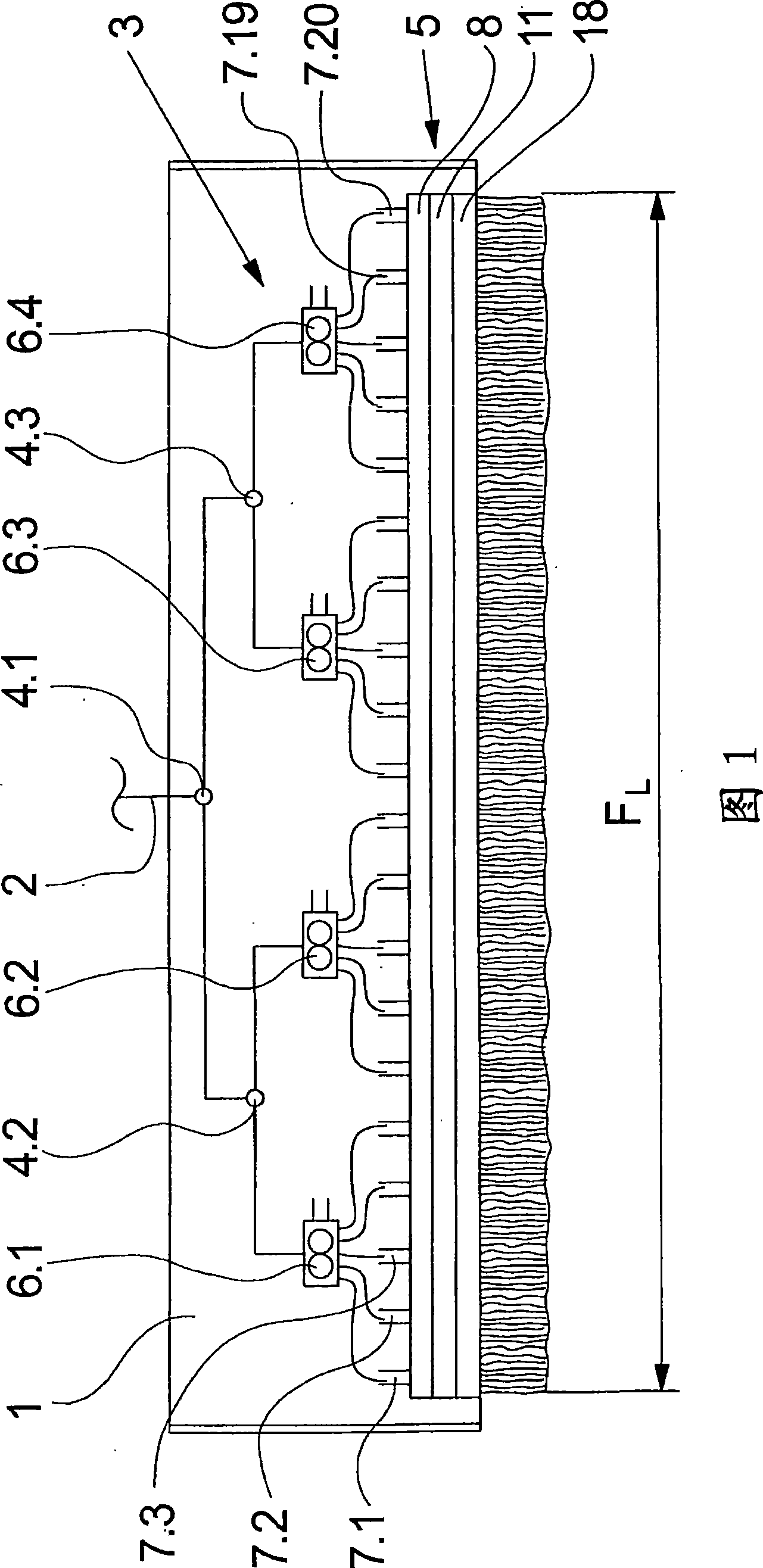
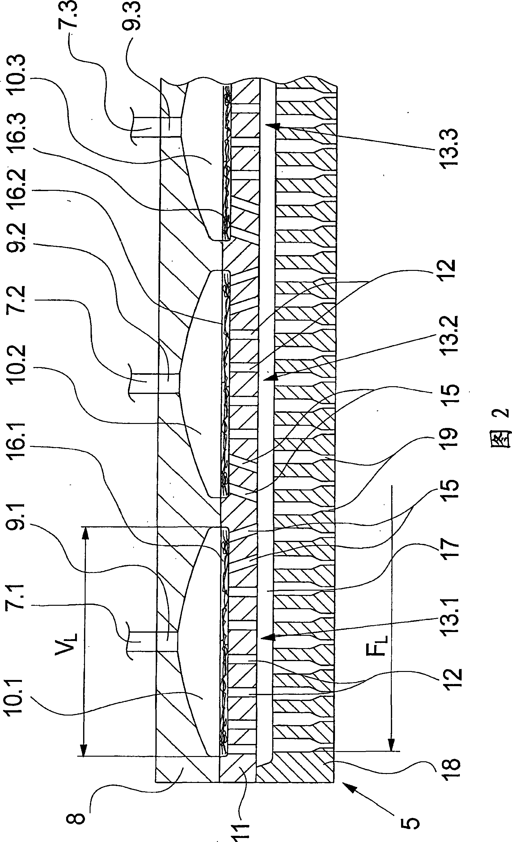
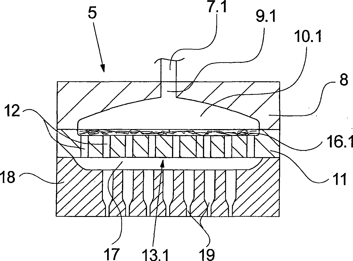
[0034] FIG. 1 schematically shows a view of a first embodiment of the device according to the invention. This embodiment shows an elongated spin beam 1 for receiving an elongated spinneret pack 5 arranged on the underside of the spin beam 1 . The spinneret assembly 5 is constructed in the form of a plate with an upper inlet plate 8 , a central perforated plate 11 and a lower spinneret 18 . The configuration of the spinneret pack 5 and the configuration of the plate parts 8 , 11 and 18 are drawn and further explained in detail below.
[0035] The spinneret pack 5 is connected to a plurality of spinning pumps 6.1, 6.2, 6.3 and 6.4 via a plurality of melt lines 7.1, 7.2, 7.3 etc. up to 7.20. The spinning pumps 6 . 1 to 6 . 4 are associated with a plurality of melt lines which are directly assigned to the inlet plate 8 . In this exemplary embodiment, a total of 5 melt lines are assigned to each spinning pump 6.1 to 6.4.
[0036] A pipe distribution system 3 is arranged inside t...
PUM
 Abstract
Description
Claims
Application Information