Optical bus

An optical bus, optical fiber technology, used in the field of optical communication and optical links

Inactive Publication Date: 2013-01-02
FINISAR
View PDF2 Cites 0 Cited by
  • Summary
  • Abstract
  • Description
  • Claims
  • Application Information

AI Technical Summary

Problems solved by technology

In practice, implementing a traditional optical bus may require the control module or computer to have separate transceivers for each peripheral

Method used


Image

  • Optical bus
  • Optical bus
  • Optical bus

Examples


Embodiment Construction

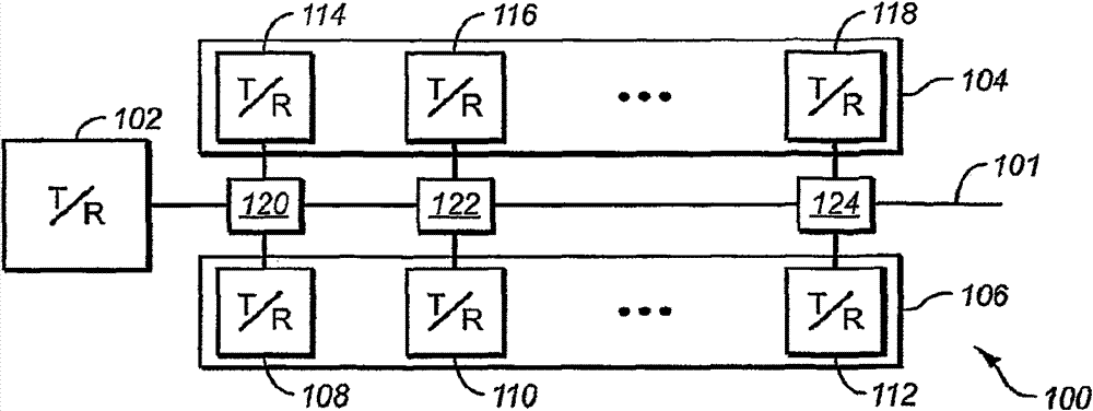
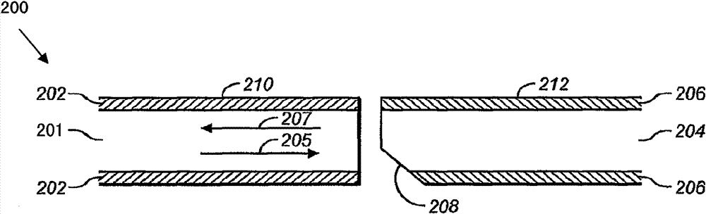
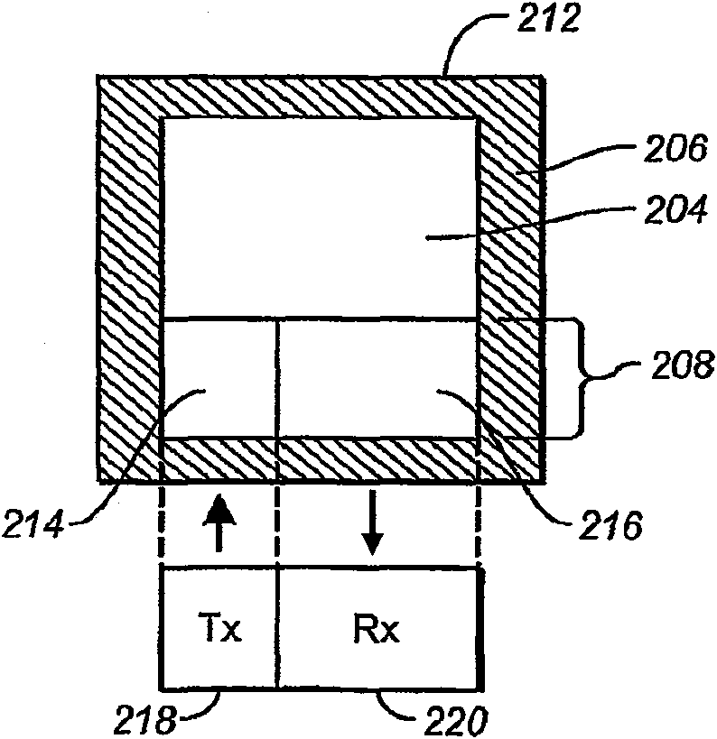
[0026] Embodiments of the present invention relate to an optical bus, and more particularly to an optical subassembly or connector that can be used in an optical bus or can be used to connect discrete optical fibers to form an optical bus. The optical subassembly of the present invention is configured such that optical cables between bus nodes can be inserted into the optical subassembly. Optical subassemblies enable specific nodes to both send and receive data over the optical bus. Some embodiments enable two-way communication over optical fibers. Using optical subassemblies or connectors, an optical bus can be formed with multiple optical fibers connected as if formed from a continuous optical fiber. The optical bus is also passive so that failure of a particular node does not cause failure of the entire optical bus.

[0027] By way of example and not limitation, embodiments of the present invention may be used in military, civilian, automotive applications, sensing applic...


PUM


Abstract

An optical bus. Optical sub-assemblies are used to connect lengths of optical fiber to form a single optical fiber that is a bus. A master transceiver may be connected to one end of the fiber and nodes can be connected to the optical sub-assemblies. Each optical sub-assembly includes a center fiber with a mirror that enables each connector to reflect optical signals out of the fiber and that enables a node to launch optical signals on the optical bus. The optical bus can also be connected with a second transceiver that may be used to deliver optical power to the attached nodes. Some nodes include two optical subassemblies to enable bidirectional communication on the optical bus.

Description

technical field [0001] The invention relates to the fields of optical communication and optical links. In particular, embodiments of the present invention relate to an optical bus and an optical sub assembly for use in the optical bus. Background technique [0002] When people think of computers, traditional desktop systems and laptops usually come to mind. Computers are generally used in schools or to solve related problems. But in the longer term, people use many different types of computers, directly or indirectly, every day. Typically, these computers are part of a system that monitors or controls peripheral components. [0003] For example, many systems in operation today are computer controlled. Usually, these computer systems are connected with external components for different purposes like data acquisition or data export. For example, a computer can be connected to multiple sensors. The data provided by these sensors can be collected and evaluated by a compute...

Claims


Application Information

Patent Timeline
Patent Type & Authority Patents(China)
IPC IPC(8): G02B6/42H04B10/278
CPCG02B6/4246G02B6/4214H04B10/278H04B10/25891
Inventor 弗兰克·莱文森
Owner FINISAR
Why Eureka
Try Eureka