Capacity-expansion groove gas-liquid disconnecting gear

A technology of a gas-liquid separation device and a capacity expansion tank, which is applied in the field of capacity expansion tanks, and can solve problems such as blockage of mesh holes, time-consuming and labor-intensive, and increased economic costs

Inactive Publication Date: 2009-06-03
GUIYANG AL-MG DESIGN & RES INST
View PDF0 Cites 4 Cited by
  • Summary
  • Abstract
  • Description
  • Claims
  • Application Information

AI Technical Summary

Problems solved by technology

Its shortcoming is that due to its simple structure, the separation of water and gas is not sufficient, and when the gas-liquid mixture is not clean, the bonded matte...

Method used


Image

  • Capacity-expansion groove gas-liquid disconnecting gear
  • Capacity-expansion groove gas-liquid disconnecting gear
  • Capacity-expansion groove gas-liquid disconnecting gear

Examples


Embodiment Construction

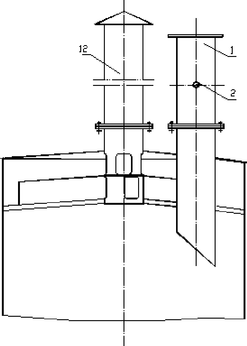
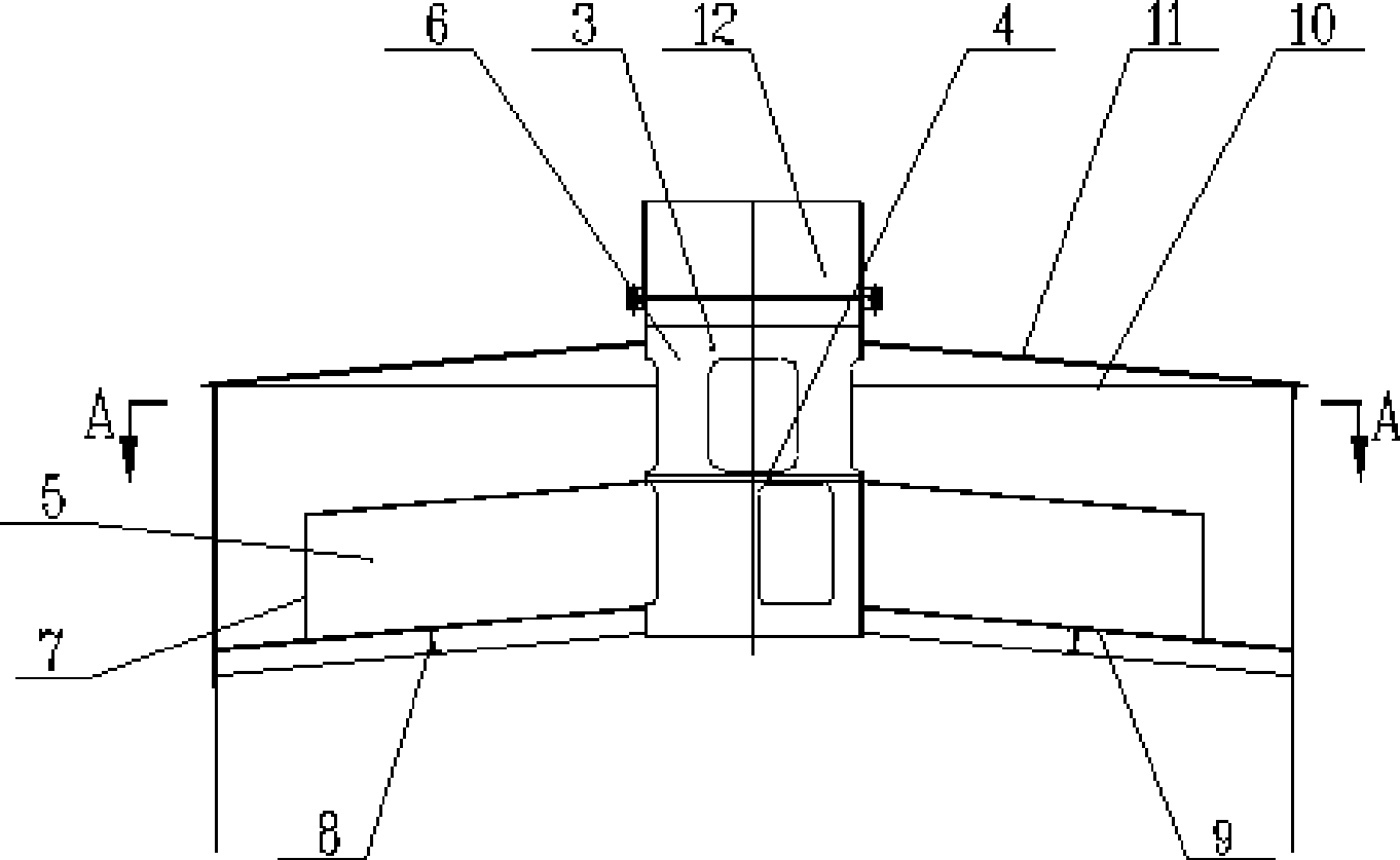
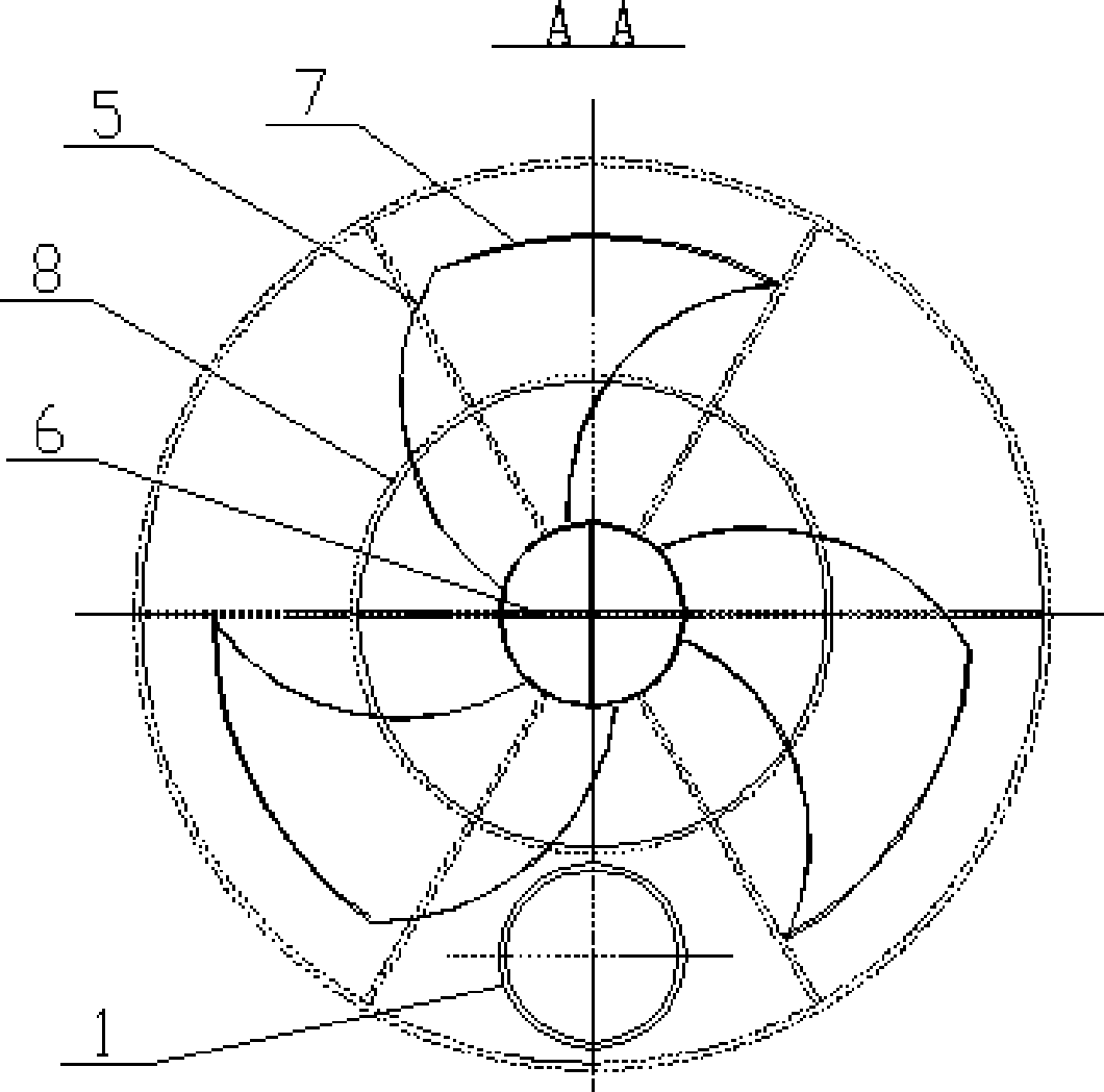
[0013] Embodiments of the present invention: a shower pipe 2 is installed in the middle of the steam inlet pipe 1, the bottom end of the inlet pipe 1 will be lower than the entrance of the cylinder 3, and a blind plate 4 is arranged in the middle of the cylinder 3 to divide the cylinder into two sections. Weld six fan-like blades 5 with a certain height on the periphery of the lower cylinder, and the diameter of the blades will be less than the inner diameter of the tank, so that it has a certain gap. Three rectangular holes are evenly distributed in the middle of the lower cylinder and the blades, four rectangular holes are evenly distributed in the upper cylinder, and a cross steel plate 6 is welded in the middle of the upper cylinder to divide the inner cavity into four small grids . Connect a steel plate 7 at the position of the rectangular hole between the two blades again. The lowermost end is surrounded by I-shaped steel to form a circular body 8, and the I-shaped stee...


PUM


Abstract

The invention discloses a capacity-expansion groove gas-liquid disconnecting gear, which comprises an inlet pipe (1), a cylinder (3). A piece of blinding plate (4) at the middle of the cylinder (3) divides the cylinder into two sections. The upper section and the lower section of the cylinder are respectively provided with a rectangle hole. The periphery of the lower section cylinder has blades (5). The upper part of the cylinder (3) is connected with an outlet pipe. The capacity-expansion groove gas-liquid disconnecting gear causes that gas comes in, goes out, goes up in a slow curve way while water drops fall, and fully plays a role in gas-liquid separation in the whole ascending process.

Description

technical field [0001] The invention relates to an expansion tank for alumina production, in particular to a gas-liquid separation device in the expansion tank. Background technique [0002] The expansion tank is a process in the alumina production process. The medium entering the tank is a mixture of gas and liquid with a certain temperature. In order to separate the gas and liquid in the tank, the water in the gas drops into the tank, and the moisture content of the gas is reduced to a reasonable state, and then enters the atmosphere through the outlet pipe. The current demister uses two orifice plates, the upper and the lower, and a steel wire mesh is enclosed in the middle to form a short tube, which is installed under the cover plate. Its disadvantage is that due to its simple structure, the separation of water and gas is not sufficient, and when the gas-liquid mixture is not clean, the bonded matter adheres to the steel wire mesh to block the mesh. It needs to be re...

Claims


Application Information

Patent Timeline
IPC IPC(8): B01D45/00F28B3/04
Inventor 孙敏
Owner GUIYANG AL-MG DESIGN & RES INST
Why Eureka
Try Eureka