Device for filtering cutting fluid

A technology of filtering device and cutting fluid, applied in the direction of filtering circuit, filtering separation, maintenance and safety accessories, etc., can solve the problems of inability to increase the height, inability to increase the total length of the fluid passage, etc., and achieve the effect of simple cleaning

Active Publication Date: 2009-06-03
BROTHER KOGYO KK
View PDF0 Cites 21 Cited by
  • Summary
  • Abstract
  • Description
  • Claims
  • Application Information

AI Technical Summary

Problems solved by technology

Cutting fluid filters used in existing machine tools cannot be increased in height
Therefore, in the conventional cutting fluid filtering device, since the overall length of the fluid passage cannot be increased, there is a problem that chips in the cutting fluid do not settle and reach the filter.

Method used


Image

  • Device for filtering cutting fluid
  • Device for filtering cutting fluid
  • Device for filtering cutting fluid

Examples


Embodiment

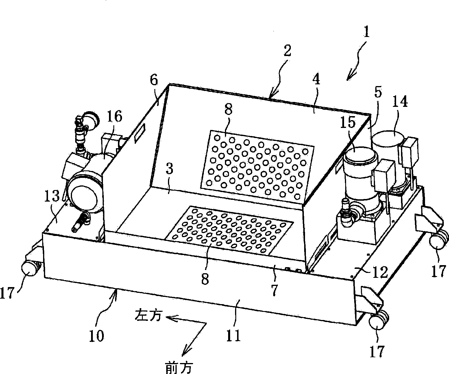
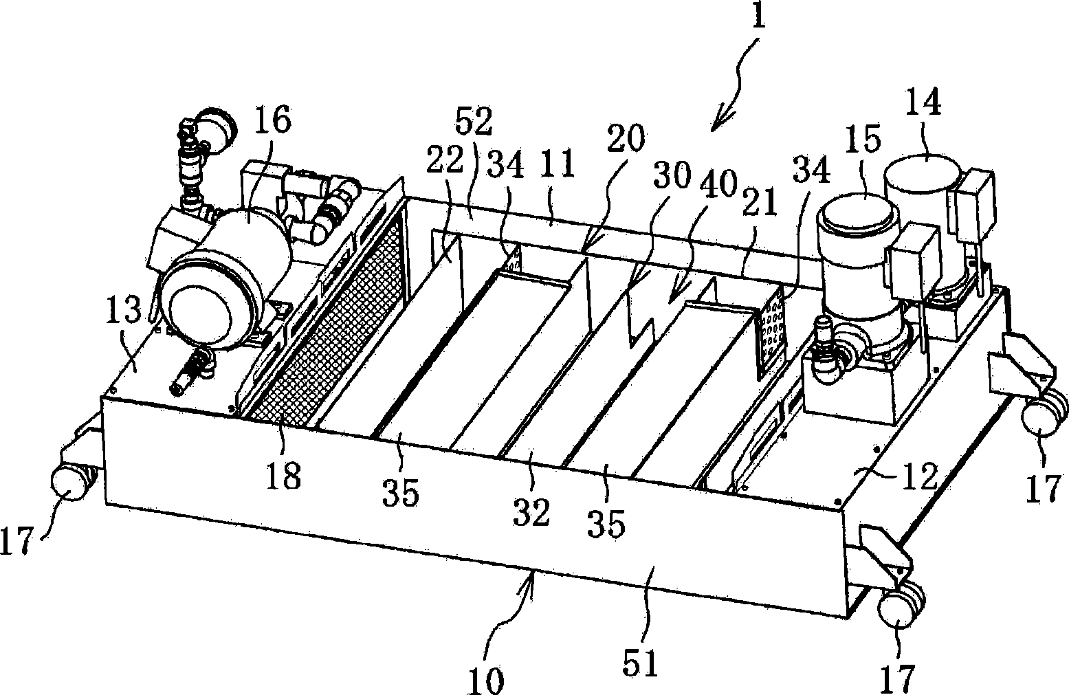
[0027] Embodiments of the present invention will be described below with reference to the drawings. like figure 1 , figure 2 As shown, the cutting fluid filter device 1 includes a guide housing 2 and a cutting fluid tank 10 .

[0028] like figure 1 As shown, the guide housing 2 includes a bottom wall portion 3 , a rear wall portion 4 , a right side wall portion 5 , a left side wall portion 6 and a mounting portion 7 . The upper surface and the front surface of the guide case 2 are open. The bottom wall portion 3 is inclined downward toward the rear. The cutting fluid flowing into the guide housing 2 flows toward the rear of the bottom wall portion 3 due to the inclination of the bottom wall portion 3 . The bottom wall portion 3 has a chip receiving plate 8 which will be described later in its central portion. The chip receiving plate 8 has many through holes (for example, a diameter of about 3.0 mm). The cutting fluid discharge part 41 of the machine tool (refer to F...


PUM


Abstract

The present invention provides a device for filtering cutting fluid, capable of availably separating and removing cutting waste in the cutting liquid after cutting treament, and availably cleaning the bottom of the reclaiming tank. The device includes a flow path forming body in the reclaiming tank, wherein the flow path forming body is provided with a connection plate and a plurality of baffles. The connection plate is parallel with the side wall of the reclaiming tank, and the baffles are spaced with each other by suitable distance in a parallel direction and are crossed with the connection plate on the square. The end portion of the different side of neighboring baffles is provided with a rabbet portion. In the device of the invention, due to the existing of the rabbet portion, the flow path of the cutting fluid is in serpentuate state along a horizontal direction, and the whole length of the flow path is increased, such that the cutting waste in the cutting fluid is deposited.

Description

technical field [0001] The present invention relates to a cutting fluid filtering device with a guide shell and a recovery tank, in particular to a cutting fluid flow path snaked along the horizontal direction formed in the recovery groove, and the cutting fluid flows in the cutting fluid flow path after cutting A cutting fluid filter device that precipitates chips in the cutting fluid during the period. Background technique [0002] When cutting is performed using a machine tool, cutting is usually performed with a tool while supplying a cutting fluid to a cutting portion of a metal workpiece. The cutting fluid cools the tool that generates heat due to frictional heat during cutting, thereby improving the life of the tool and the machining accuracy of the workpiece. The cutting fluid used in the cutting process contains impurities such as chips generated during the cutting process. The cutting fluid filter has multiple functions described below. As the first function, th...

Claims


Application Information

Patent Timeline
Patent Type & Authority Applications(China)
IPC IPC(8): B23Q11/00B01D21/00B01D36/04
Inventor 龟山郁雄
Owner BROTHER KOGYO KK
Why Eureka
Try Eureka