Injection molding part producing method

A technology of injection molding and injection molding machine, which is applied in the field of device of injection molding parts

Active Publication Date: 2009-06-03
KRAUSSMAFFEI TECH GMBH
View PDF4 Cites 3 Cited by
  • Summary
  • Abstract
  • Description
  • Claims
  • Application Information

AI Technical Summary

Problems solved by technology

[0005] It is problematic in injection molding machines of the type described above that during operation the temperatures of the mold halves fixed on the mold clamping plates and of the mold halves fixed on the central mold support or indexing plate must be adjusted during operation

Method used


Image

  • Injection molding part producing method
  • Injection molding part producing method
  • Injection molding part producing method

Examples


Embodiment Construction

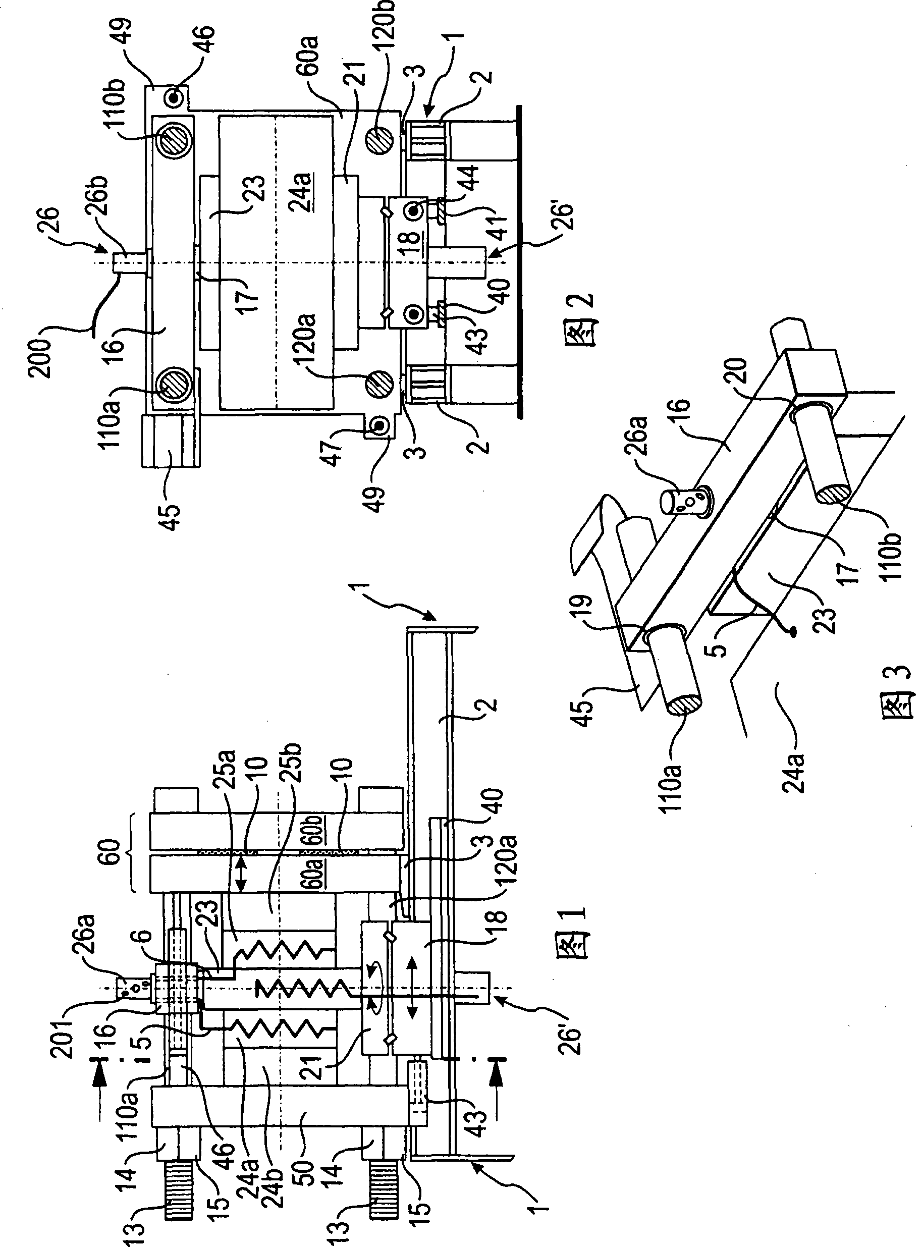
[0016] According to FIGS. 1 to 3, a frame 1 is provided with two longitudinal supports 2 spaced apart from one another, on which a fixed mold clamping plate 50 and a mold clamping plate 60 movable on a slide 3 are arranged. . The movable mold clamping plate 60 comprises an actual mold clamping plate 60a and a pressure plate 60b including a pressure cushion 10 in between which can be applied by means of a pressure medium source not shown here. to closing pressure. Between the mold clamping plates extend upper struts 110a and 110b and lower struts 120a and 120b. These struts are fixed at one end in the fixed mold clamping plate 50 and pass through the fixed mold clamping plate 50 with their other end. At the protruding end, each strut has a toothing 3 in which the interlocking jaws 14 and 15 can be moved in and out (the moved in position can be seen in the figure). For moving the movable mold clamping plate 60 relative to the fixed mold clamping plate 50 , hydraulic actuating...


PUM


Abstract

The present invention describes a device for producing an injection molding part, including a mold support (23) and one or more injection molds (24, 25) with half-molds (24a, 25a) that are attached on the mold support (23), where separate temperature adjustment (64, 99a, 99b) is provided for the mold support (23) and the half-molds (24a, 25a). By means of setting a separate temperature adjustmentfor a positioning plate or a cube-shaped mold support and each half-mold fixed on the mold support, it is able to avoid mold support size change or to only allow a size change on each mold clamping plate independent of the half-mold temperature adjustment. Thus, each half-mold on the mold support may align to the corresponding half-mold on the mold clamping plate accurately.

Description

technical field [0001] The invention relates to a device for injection molded parts and an injection molding machine with such a device. Background technique [0002] Known from EP1 155 802 B1 is an injection molding machine in which a plurality of struts extend between two mold clamping plates, a crossbeam is respectively mounted on the upper two struts and the lower two struts, which can be moved along each The struts move relative to each mold clamping plate and relative to each other. A mold support is clamped between the beams and provided with mold halves which can be combined with mold halves fastened on mold clamping plates in order to form the cavity of the molded part. The mold support in the center of each beam is movable in the longitudinal direction of the machine. Furthermore, a drive is provided for the rotation of the central mold support about a vertical axis. On both beams there is a swivel device or a swivel distributor with a plurality of channels or d...

Claims


Application Information

Patent Timeline
IPC IPC(8): B29C45/72B29C45/73B29C45/78B29C45/17B29C45/06
CPCB29C45/045B29C45/1628B29C33/0083B29C45/72B29C45/74
Inventor M·格鲁贝尔A·莱特贝格尔
Owner KRAUSSMAFFEI TECH GMBH
Why Eureka
Try Eureka