LCD splicing display device and large screen splicing display system thereof

A technology of splicing display and large screen, applied in the field of LCD display, can solve the problem of image quality deterioration of the display screen, and achieve the effect of easy implementation, simple device principle, and elimination of panel borders

Inactive Publication Date: 2009-06-03
GUANGDONG VTRON TECH CO LTD
View PDF1 Cites 8 Cited by
  • Summary
  • Abstract
  • Description
  • Claims
  • Application Information

AI Technical Summary

Problems solved by technology

The Chinese utility model patent "optical fiber magnified display" with application number 00225268.6 proposes the concept of optical fiber magnified display, which uses optical fibers with different thickness at both ends to amplify the image geometrically. However, due to the large-area optical fiber arrangement process Separated from the individual optical fiber, it is easy to cause serious deterioration of the image quality of the display screen

Method used


Image

  • LCD splicing display device and large screen splicing display system thereof
  • LCD splicing display device and large screen splicing display system thereof
  • LCD splicing display device and large screen splicing display system thereof

Examples


Embodiment 1

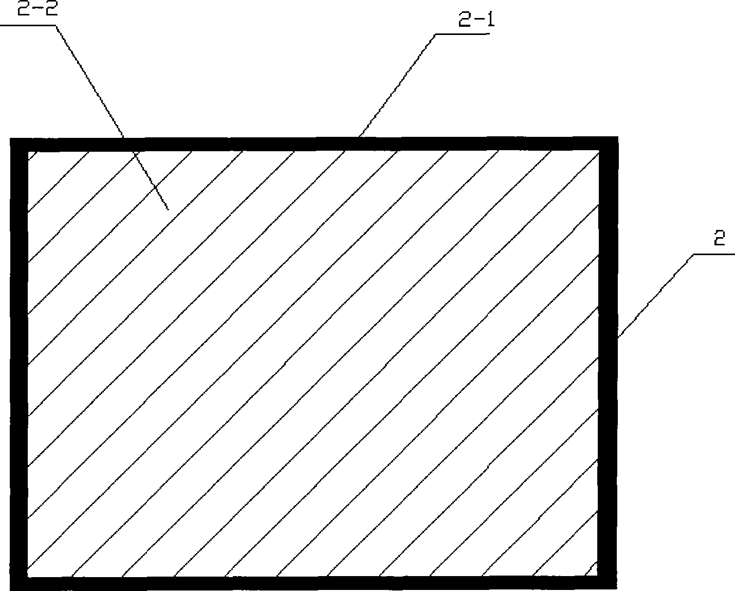
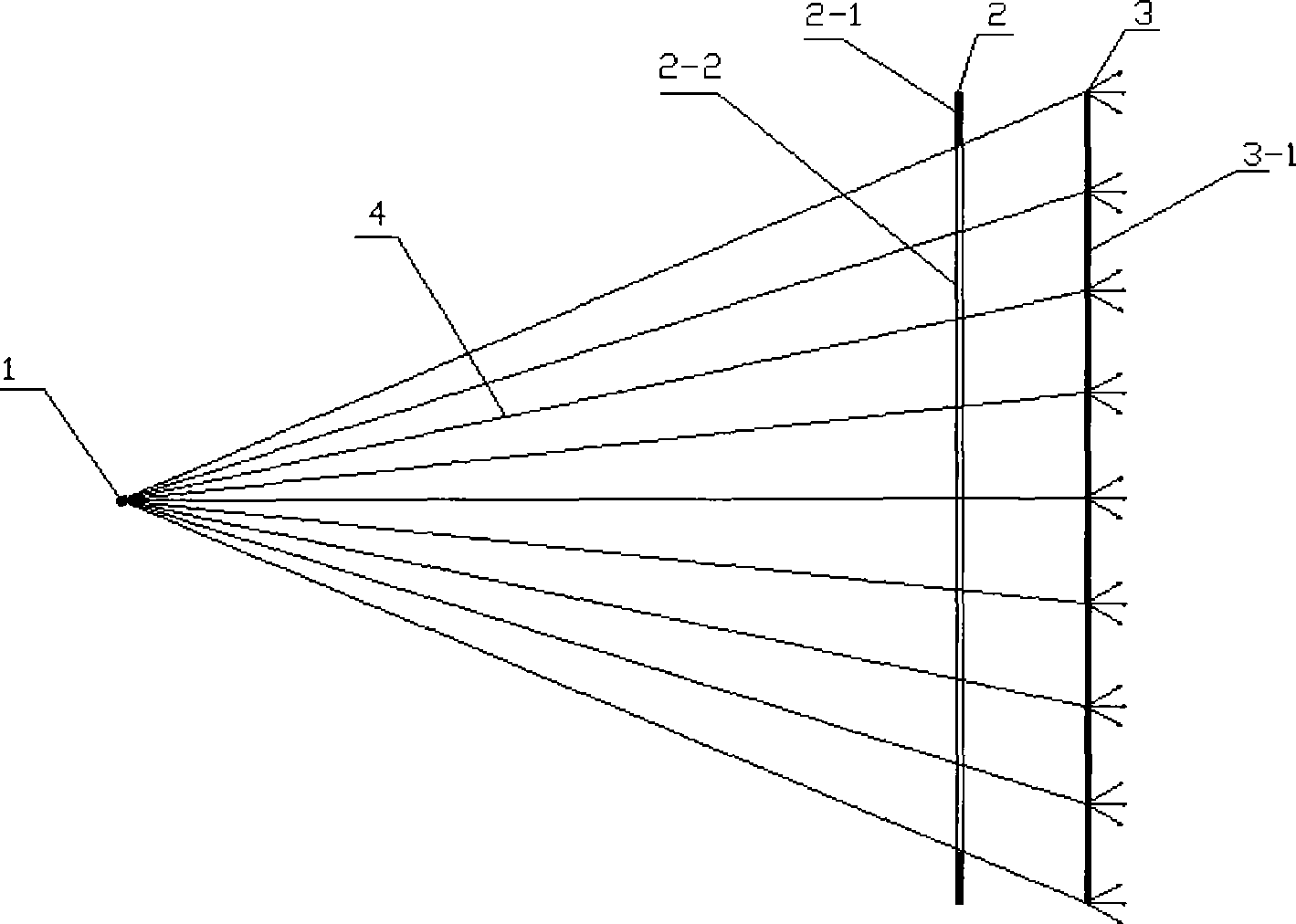
[0031] An LCD splicing display device in this embodiment, such as figure 1 As shown, the LCD panel 2 is surrounded by a panel frame 2-1, and the middle part is a picture 2-2. The structure of the LCD splicing display device is as follows: figure 2 As shown, it consists of a point light source 1, an LCD panel 2 and a rear projection screen 3 arranged in sequence according to the optical path, wherein the LCD panel 2 is surrounded by a panel frame 2-1, and the middle part is a picture 2-2; the point light source 1 is placed on the picture 2 -2 on the vertical center line; wherein the projected picture 3-1 on the rear projection screen 3 is the projected picture obtained after the picture 2-2 on the LCD panel is projected by a point light source.

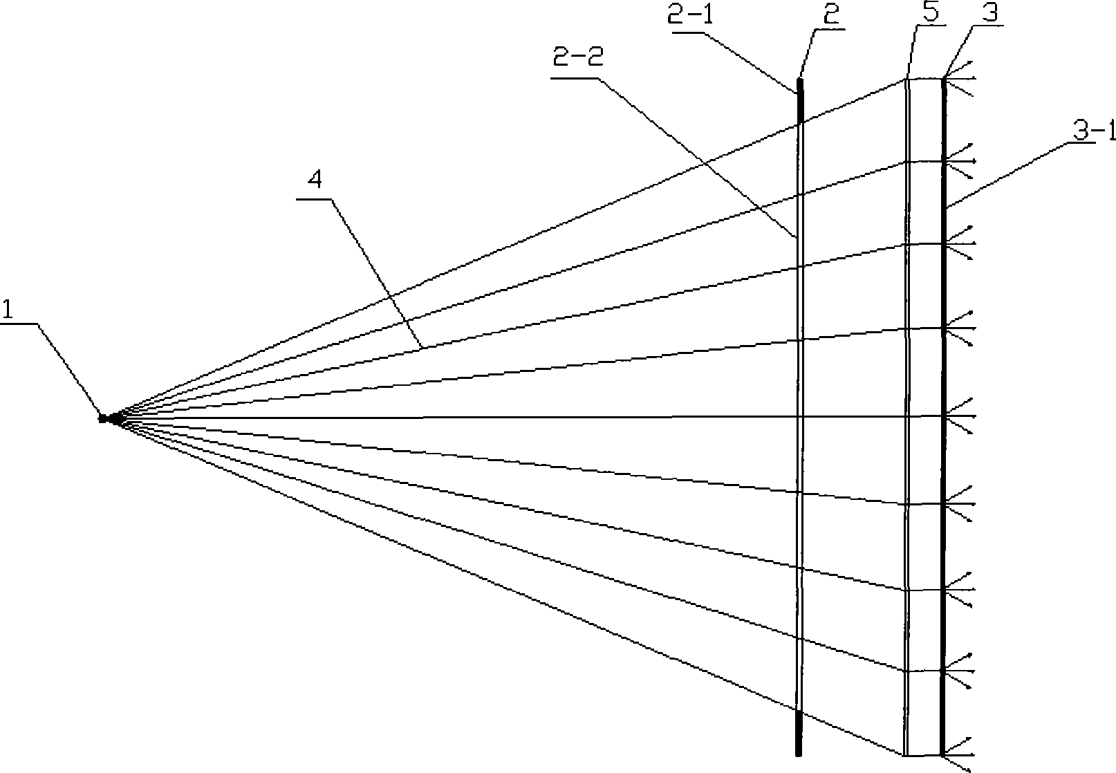
[0032] Such as image 3 As shown, in order to improve the display effect on the rear projection screen 3 , a collimating lens 5 for collimating the light beam 4 incident on the rear projection screen 3 may be provided between the LC...

Embodiment 2

[0036] An LCD splicing display device in this embodiment, such as Figure 5 As shown, there is a panel frame 2-1 around the LCD panel 2, a plurality of discrete pictures 2-2 in the middle part, and a picture interval 2-3 between any two adjacent pictures 2-2. The structure of the LCD splicing display device is as follows: Image 6 As shown, it consists of a point light source 1, an LCD panel 2 and a rear projection screen 3 arranged in sequence according to the optical path, wherein the LCD panel 2 is surrounded by a panel frame 2-1, and the middle part is a plurality of discrete screens 2-2; each discrete screen A point light source 1 is placed on the vertical center line of 2-2; the projected picture 3-1 on the rear projection screen 3 is the projected picture obtained after the picture 2-2 on the LCD panel is projected by the point light source.

[0037] The width of the frame interval 2-3 is greater than or equal to twice the width of the frame 2-1 of the LCD panel.

[0...

Embodiment 3

[0042] This embodiment is an LCD large-screen splicing display system, which is formed by splicing the LCD splicing display devices of the above-mentioned embodiment 1 or embodiment 2, respectively as follows Figure 9 with Figure 10 As shown, the projection screens 3-1 of any two adjacent LCD splicing display devices on the rear projection screen 3 are connected to each other to form an overall large projection screen, which completely blocks the splicing screen 6 generated by the LCD splicing, thus forming an infinite stitching display system.

[0043] The LCD splicing display devices on the above-mentioned LCD large-screen splicing display system use one rear projection screen independently, or multiple LCD splicing display devices share one rear projection screen.


PUM


Abstract

The invention provides an LCD splicing display device and a large screen splicing display system thereof. The device consists of a spot light source, LCD panels and a rear projection screen which are arranged along a light path sequentially. Each LCD panel displays one or a plurality of discrete pictures, any two adjacent pictures are spaced; each picture corresponds to one spot light source which is disposed on the vertical center line of the picture; and the spot light source projects the display picture of the LCDs to the rear projection screen for display. The device and the system can effectively eliminate a splicing seam of the panel frame while splicing the LCD panels, and the device has simple structure and can be easily realized.

Description

technical field [0001] The invention relates to the technical field of LCD display, in particular to an LCD splicing display device and a large-screen splicing display system thereof. Background technique [0002] In recent years, with the rapid development of large-size LCD panels, LCD displays have gradually become the mainstream of display technology due to their advantages of ultra-thin, light weight, no radiation, and stable performance, and are gradually replacing CRT as the mainstream of displays. Although the super-sized LCD can be 80 inches or even 100 inches, it still cannot meet the requirements of users in occasions that require large-screen display (such as monitoring rooms, etc.). The field emerges. [0003] Due to the requirements of the surrounding driving circuit and production process, the LCD panel needs to reserve a certain space around the display image, and the image cannot be displayed to the edge area of ​​the panel. Generally, the width of this area...

Claims


Application Information

Patent Timeline
IPC IPC(8): G09F9/35G02F1/13
Inventor 骆健忠孟凡华
Owner GUANGDONG VTRON TECH CO LTD
Why Eureka
Try Eureka