Combing machine with a reserve reel trough

A storage tank and combing machine technology, which is applied in the field of combing machines, can solve the problems of lifting heavy laps and achieve the effect of reducing the burden

Inactive Publication Date: 2009-06-03
ZHUOLANG INTELLIGENT MACHINERY CO LTD
View PDF1 Cites 4 Cited by
  • Summary
  • Abstract
  • Description
  • Claims
  • Application Information

AI Technical Summary

Problems solved by technology

At the latest when changing the unwinding rolls, the storage chute has to be raised to a higher operating position, thus creating the problem of lifting heavy rolls

Method used


Image

  • Combing machine with a reserve reel trough

Examples


Embodiment Construction

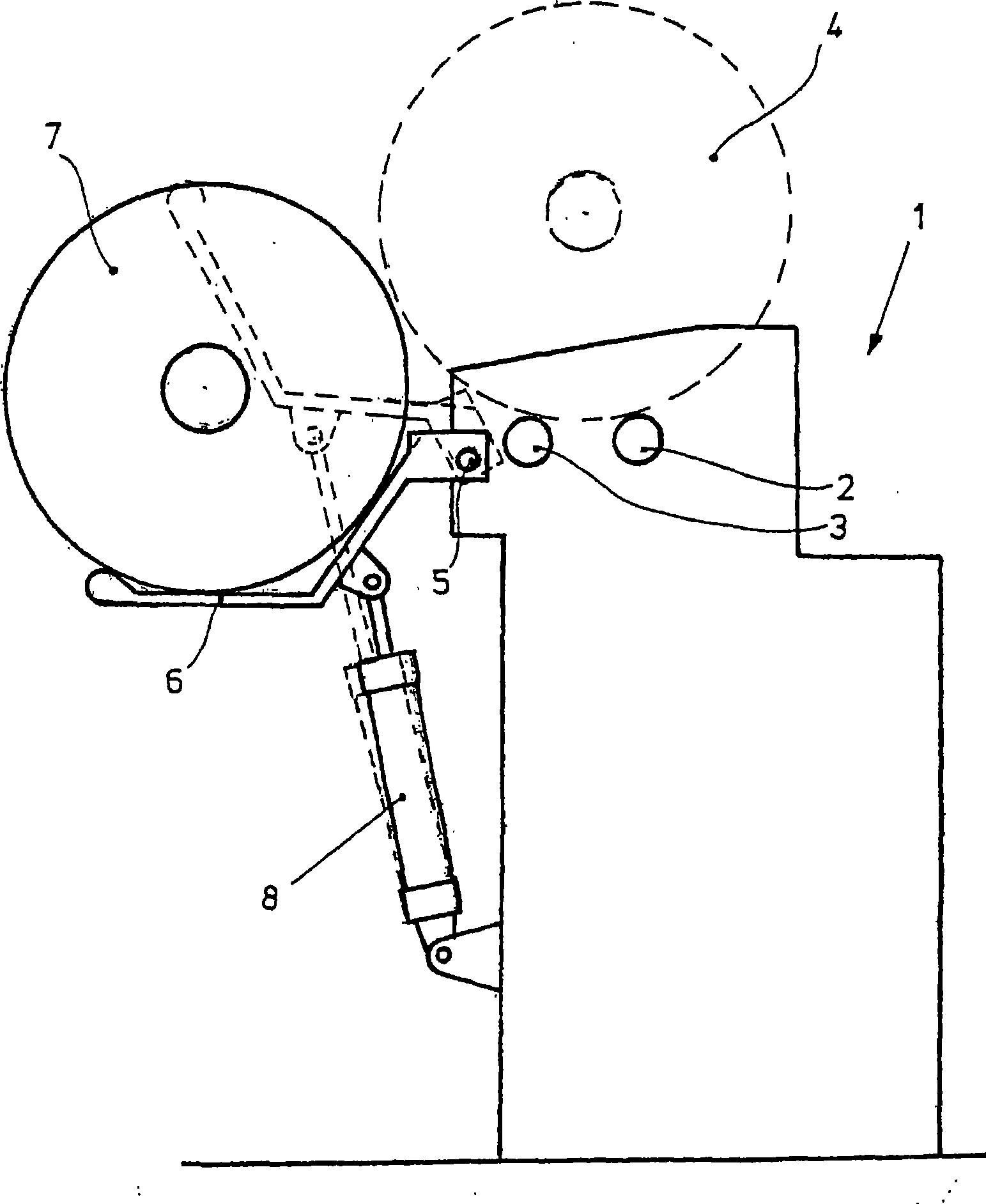
[0012] Only the outline of the frame of the comber 1 is shown. However, two winding rollers 2 and 3 are shown, on which a working lap 4 is placed and which is unwound while being fed to a not shown comber nipper arrangement .

[0013] On the back of the frame, a roll chute 6 in which a reserve roll 7 is stored is pivotally mounted on the pivot shaft 5 . The store lap rack is connected to an energy store, which is supported on the frame, here the energy store is the cylinder / piston unit 8 . The means for driving the cylinder / piston unit are not shown here. In common usage, these devices include pneumatic or hydraulic pressure sources and control slides.

[0014] When pressure is applied to the drive cylinder / piston unit 8 , the cylinder / piston unit 8 pivots the supply roll trough 6 upwards so that the supply roll located therein rolls onto the winding rollers 2 , 3 .

[0015] If it is desired to manually replace an unwound lap with a new lap, the pressurization of the cylin...


PUM


Abstract

In order to relieve the operator of a combing machine from having to handle the heavy comb reels (4, 7), a mechanically operated reserve reel trough (6) is provided. It can be lowered to such a level that it can easily roll comb reels, even from the lowest position into which they are delivered by the combing machine, into the reserve reel trough. On the other hand it can be raised to such a high level that the reserve reels roll by themselves into working position on the reel cylinders (2, 3). The mechanical operation is effected preferably by a fluidically (pneumatic or hydraulic) operable work element with cylinder and piston which is arranged between the frame of the combing machine and the reserve reel trough.

Description

technical field [0001] The invention relates to a combing machine having at least one storage chute and comprising winding rollers, in which storage laps can be stored and by means of which the laps can be unwound. Background technique [0002] Cotton laps are produced on laps or winders for processing on combers. Various embodiments of these machines are known, which transport combed laps at different heights. Typically, laps weighing up to 25 kg are transported to the comber on carriages, so it is obviously unwise to have an operator handling the laps. On the comber, the laps are stored in storage racks. [0003] These storage racks are usually placed lower so that the laps can be transported from the carriages to the storage racks without having to be lifted by the operator. At the latest when changing the unwinding laps, the storage chute must be raised to a higher operating position, so that the problem of lifting heavy laps arises. [0004] EP 0 593 391 B1 disclose...

Claims


Application Information

Patent Timeline
Patent Type & Authority Applications(China)
IPC IPC(8): D01G19/08
CPCD01G19/08
Inventor 马蒂亚斯·朔伊夫勒海纳·克洛伊伦
Owner ZHUOLANG INTELLIGENT MACHINERY CO LTD
Why Eureka
Try Eureka